Quiz buzzers are used often at places like educational institutions and game shows, where it is required for the organizers to know who pressed the button first. Conventional systems require human intervention to decide which team has pressed the button and this system can be erroneous and even biased. Another problem arises when two members pressed the button at a negligible interval and it is difficult to guess who has pressed the buzzer first. Here in this project, I designed an Automatic Quiz Buzzer System in which, when more than one team presses the buzzer, the delay between the two button presses is accurately taken into account and the corresponding number is displayed. I have designed the circuit using 8051 microcontroller, which scans the input from push buttons and displays the corresponding number on a display device (7-Segment Display). It is a simple circuit with minimum number of components and sans any complexities. Even though this system is designed for only for 8 teams, more teams can be added by using another set of 8 push buttons.
Principle Behind the Quiz Buzzer Circuit
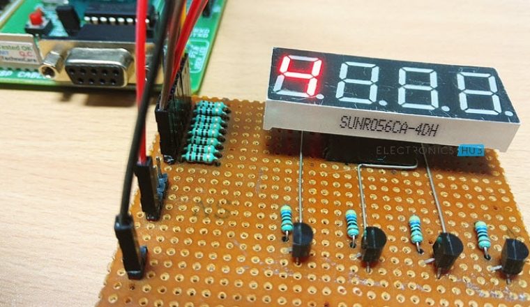
The 8 Channel Quiz Buzzer Circuit using Microcontroller is a simple embedded system with a set of 8 push buttons being the input devices, a microcontroller as the main controller and the output devices being a buzzer and a display. The whole operation is carried out by a microcontroller through a program written in C language and dumped inside the microcontroller. When one of the buttons is pressed, the buzzer starts ringing and the corresponding number is displayed on the 7 segment display.
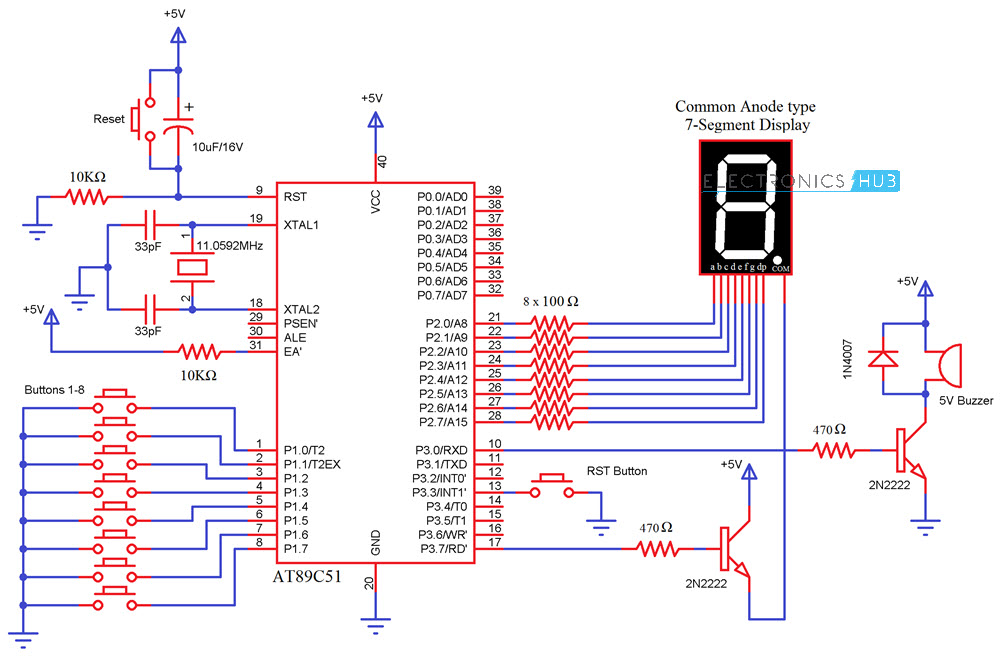
Circuit Diagram of 8 Player Quiz Buzzer using Microcontroller
Components Required
AT89C51 (8051 Microcontroller) 7 Segment Display (Common Anode is used in this project) Push Buttons – 10 10KΩ Resistors – 2 100Ω Resistors – 8 470Ω Resistors – 2 2N2222 NPN Transistors – 2 5V Buzzer 1N4007 Diode 10μF Capacitor 33pF Capacitors – 2 11.0592 MHz Crystal 8051 Programmer 5V Power Supply
Design Process
The whole design process involves five steps.
Quiz Buzzer Circuit Design
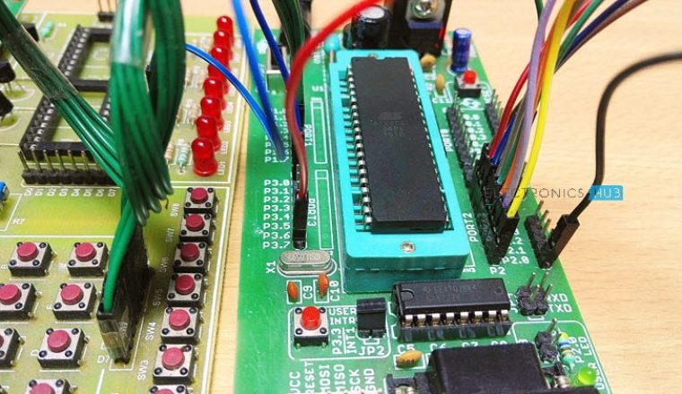
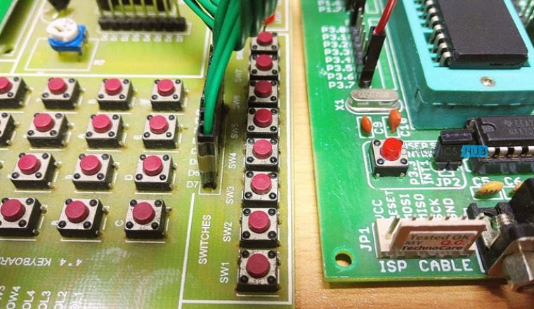
The circuit involves using five major components – 8051 Microcontroller, SPST Push Buttons, a buzzer and a common anode 7 segment display. The microcontroller used in this case is AT89C51, an 8 bit microcontroller manufactured by Atmel (now Microchip). Reset Circuit Design: The reset resistor is selected such that the voltage at the reset pin, across this resistor is at minimum of 1.2V and the width of the pulse applied to this pin is greater than 100 ms. Here we select a resistor of 10KΩ and a capacitor of 10μF. Oscillator Circuit Design: The oscillator circuit is designed using a crystal oscillator of 11.0592 Mhz and two ceramic capacitors each 33pF. The crystal is connected between pins 18 and 19 of the microcontroller Microcontroller Interfacing Design: The set of 8 push buttons are interfaced to port P1 of the microcontroller and a buzzer is interfaced to the port pin P3.3. The 7 segment display is interfaced to the microcontroller such that all the input pins are connected to port P2. Microcontroller Code: The code can be written using C language or assembly language. Here, I have written the program in C language using Keil μVision software. This is accomplished by the following steps: Once the code is compiled and a hex file is created, next step is to dump the code into the microcontroller. This can be done with an 8051 Microcontroller Programmer.
CODE
How Quiz Buzzer Circuit Works?
Once the circuit is powered, the compiler will initialize the stack pointer and the variables having the non-zero initial values and perform other initialization process and then calls the main function. It then checks if any of the buttons is pressed. In other words the microcontroller scans for any of its input pins at port P1 to be zero or at logic low level. In case a button is pressed, the display function is called by passing the corresponding number. The microcontroller then sends the relevant signals to the port connected to the 7 segment display. The microcontroller will turn on the buzzer for a second and turns it off but the number will be continously displayed on the 7 segment display until the RST button is pressed.
Applications of Quiz Buzzer Circuit
Comment * Name * Email * Website
Δ
![]()
![]()
![]()
![]()
![]()

