Active Audio Crossover Circuit Principle:
Generally audio crossover circuits are of two types, active crossover circuit and passive crossover circuit. Passive audio crossover circuits are very simple and they use passive components to separate the frequency bands from audio signal, but in this passive crossover circuit considerable amount of energy is wasted and also distortion is induced. Active crossover circuits use active components to separate the complex audio signal into separate frequency bands and this crossover circuits does not suffer from the above mentioned drawbacks. Active crossover circuits are advised to use for audio systems. Crossover circuits split the input audio signal into 2 bands, a low frequency band and a high frequency band. These two separated frequency bands are separately amplified by using 2 power amplifier stages. One stage is tuned to the low frequency band and other is tuned to the high frequency band respectively.
Active Audio Crossover Circuit Diagram:
Circuit Components:
LM833Dual High-Speed Audio Operational Amplifier – 2 24k Resistors (1/4 watt) – 7 6.2k Resistors (1/4 watt) – 2 6.8nF capacitors – 3 Audio jack Connecting wires Breadboard
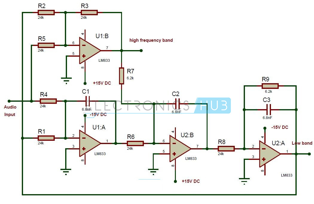
Active Audio Crossover Circuit Design:
The main component in the above crossover circuit is LM833 Dual audio operational amplifier which was manufactured by the National Semiconductors. The crossover circuits needs 4 operational amplifiers, so we need 2 lm833 ICs to construct the circuit. This active crossover circuit can be divided into 2 sections, high pass filter section and low pass filter section. The operational amplifier U2:A forms a first order low pass butterworth filter and it provides low band frequencies at pin1. Audio operational amplifier U1:B provides high band frequencies at pin7. The frequency of the given active crossover circuit is calculated using the formula Fc = 1/(2πRC) For the given components the frequency of the crossover circuit is 1 KHz.
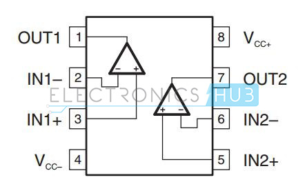
LM833 Dual Audio Operational Amplifier:
This IC is a dual operational amplifier with high performance specifications for the use in data signal and audio applications. This IC operates with a wide range single and dual supply voltage. The operating voltage of this IC is from +/- 5V to +/- 18V DC. It provides high gain bandwidth. Additional features include large output voltage swing with no dead band crossover distortions, low harmonic distortion and low input offset voltage. These ICs are most widely used in HiFi systems. Features:
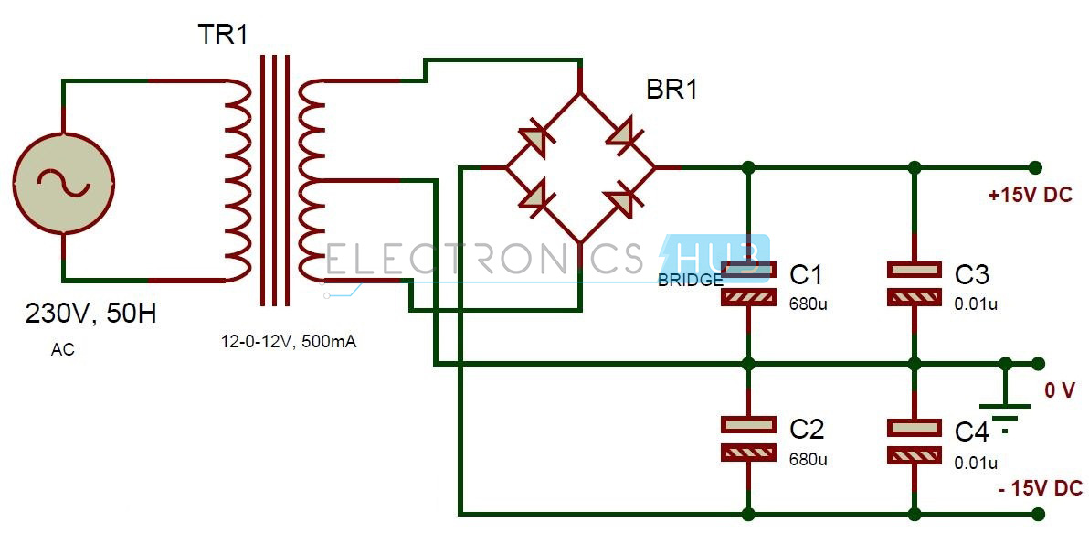
Dual Power Supply Circuit Design:
This circuit is used to provide +15V and -15V DC supply to the circuit. Here the center tapped transformer step downs the 230V, 50 Hz to 12-0-12V, 500mA. Diode Bridge is made with four 1n4007 diodes. This bridge provides pulsating DC from AC voltage. Here capacitors are used to filter the AC ripples. Circuit Components:
12-0-12V, 500mA center tapped transformer Diode bridge – 1A 680uF Electrolytic capacitors – 2 0.01uF capacitors – 2
How to Operate Active Audio Crossover Circuit?
Active Audio Crossover Circuit Applications:
Limitations of the Circuit:
This circuit is theoretical and may require some changes to implement it in practical.
Comment * Name * Email * Website
Δ
![]()
![]()
![]()
![]()
![]()

