Home Automation is a concept where a single device is used to control many aspects of a home like switching on and off different appliances, monitoring temperature, fire alarms, garage doors etc. In this project, a remote control is used to control (simply ON and OFF) several appliances or devices, thus achieving a simple home automation system. Remote controls are one of the commonly found devices in almost all homes. They help us operating an appliance like TV, Air Conditioning, VCR, etc. The main feature of a remote control is that it is specific to a device. For example, a TV remote control unit can only be used for that corresponding TV. But in this project, we have designed an Arduino based Home Automation using TV Remote, where a single remote is used to control 4 different devices (possible to control more devices). The project is based on Arduino UNO and more details of the project are mentioned below.
Circuit Diagram
Components Required
Arduino UNO board TSOP 1738 IR Remote Control Receiver 1 KΩ Resistor X 4 2N2222 NPN Transistor X 4 1N4007 Diode X 4 12 V Relay X 4 Remote Control Prototyping board (Bread board) Connecting wires 12 V Power supply
Component Description
Arduino UNO Arduino UNO forms the main controlling part of the circuit. UNO has 13 digital I/O pins and hence, it is possible to control 13 different devices at once. If the requirement is to control more number of devices, boards like Arduino Mega can be used. TSOP1738 TSOP1738 is a Receiver module for IR Remote controls with a carrier frequency of 38 KHz. It consists of a Photo detector and signal demodulator in a single package and the output can be directly used by a microcontroller.
4 – Channel Relay Board A Relay helps in controlling a large appliance with the help of a microcontroller. In this project, a 4 – channel relay board is used to control four loads. The necessary components like power on LED, switching transistor, base current limiting resistor, Relay on LED, flyback diode and male headers for power and input connections are already embedded on the board.
Caution: We should be very careful when using a relay with AC mains supply. Remote Control A standard mini remote control is used in this project to give the various key inputs. The remote has all the numeric keys, volume up – down, channel up – down, menu and some additional keys.
How to Design Arduino based Home Automation using TV Remote Circuit?
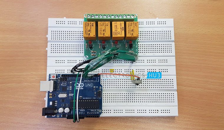
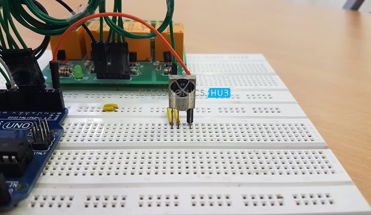
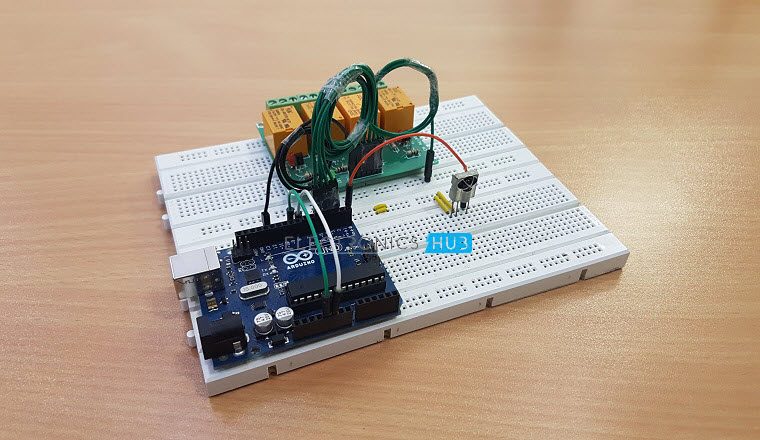
From the circuit diagram, it is clear that the design of the circuit is very simple and requires very few connection. The design of the circuit is explained below. The main component of the project is the TSOP1738 receiver. It is a three pin device where the three pins are GND, VS and OUTPUT. The VS pin is connected to the 5V supply. The output pin is connected to Pin 11 (or any other digital pin) of Arduino UNO. We are using a 4 – channel relay module in this project in order to control 4 different loads. Since the board has all the necessary components like transistors, LEDs etc. all we need to do is to connect the 4 inputs on the relay board to 4 digital I/O pins of Arduino. More detailed connection can be found in the circuit diagram.
Working of Arduino based Home Automation using TV Remote
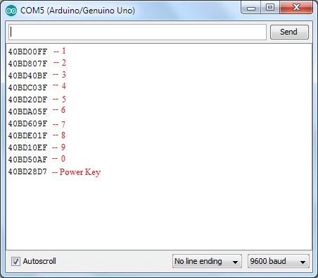
Home automation is an in demand concept where a single device will control different appliances of a home. Additionally, different aspects like temperature, humidity, security etc. can also be monitored using that device. In this project, a simple home automation system where the system controls 4 different appliances with the help of a TV Remote. The working of the project is explained here. The main component of the project is TSOP1738 IR Receiver Module. This module has a built – in photo receiver, band pass filter and demodulator and the output of the module can be readily read by a microcontroller. TSOP1738 supports a carrier frequency of 38 KHz. Hence, the carrier frequency of the source i.e. the remote control must be in the range of 38 KHz for it to demodulate. First, we will decode the data from the remote control using TSOP1738 and Arduino UNO. For that, we need to use a special library called “IRremote”. We need to download this library from https://github.com/z3t0/Arduino-IRremote and place it in the libraries folder of Arduino. The next step is to decode the data of each key of the remote. For this, we are going to use some functions in the “IRremote” library. The following program will help us in decoding the data from each key of the remote. NOTE: The following program is an example sketch from the “IRremote” library.
When this sketch is run in Arduino, we can monitor the data on the serial terminal for each key pressed on the remote. The following image shows the decoded HEX values of keys 1 to 9, 0 and power key respectively.
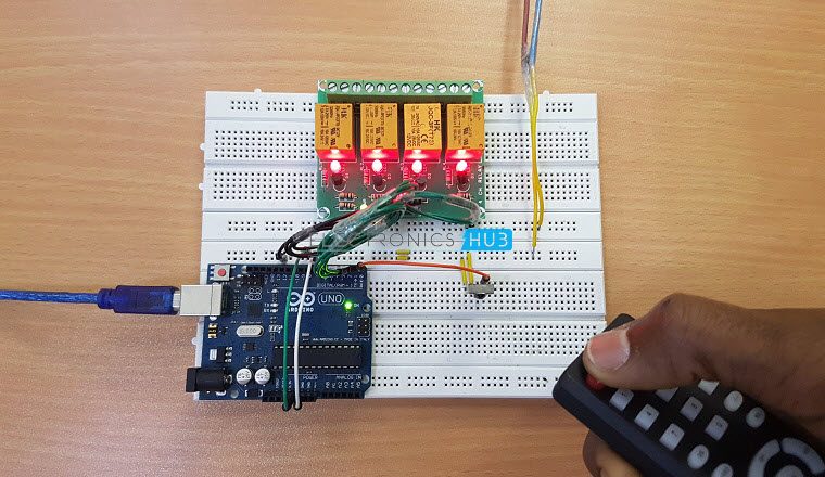
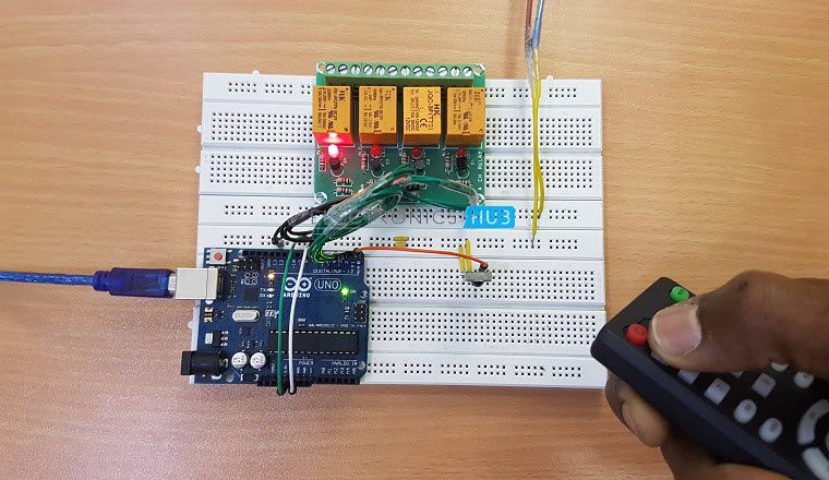
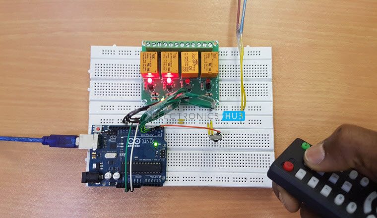
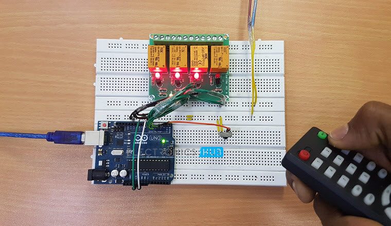
After decoding the keys, we will write the code for our final home automation system using Power key and numeric keys 1 to 4 to control 4 loads. Numeric keys will control individual loads i.e. key 1 can be used to turn ON or OFF load 1 and so on. Power key will turn ON or OFF all the loads at once. In the code, we will compare the pressed key against the decoded values which we got earlier. If the key is matched, the corresponding load is turned ON. If the same key is pressed once again, the load is turned OFF. Similar operation is applicable for all the other keys. Code:
Application
A simple project, where an Arduino based Home Automation using TV Remote is designed here which uses Arduino UNO, Relay and an old TV Remote. The project is demonstrated with 4 loads but can be increased to even more loads. Since the controlling device is a TV remote, the design of the project is very simple and the application is also very easy.
Construction and Output Video
Comment * Name * Email * Website
Δ
![]()
![]()
![]()


![]()
![]()

