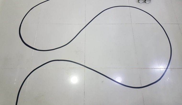
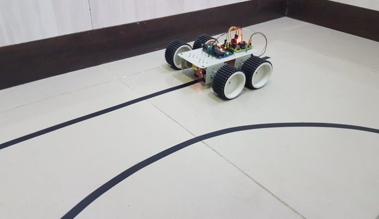
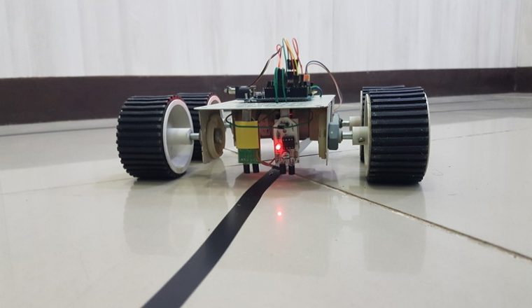
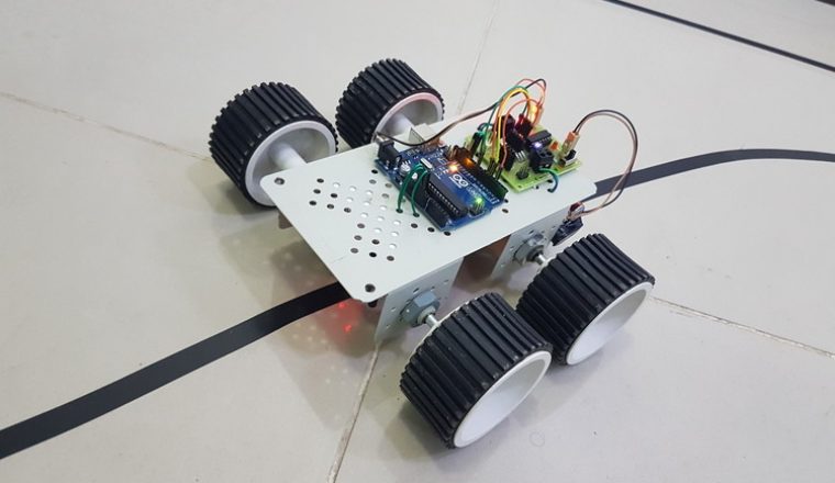
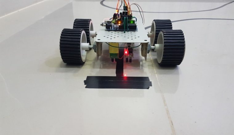
Large line follower robots are usually used in industries for assisting the automated production process. They are also used in military applications, human assistance purpose, delivery services etc. Line follower Robot is one of the first robots that beginners and students would get their first robotic experience with. In this project, we have designed a simple Line Follower Robot using Arduino and some other components. Arduino Line Follower Robot pathArduino Line Follower Robot 1Arduino Line Follower Robot 2Arduino Line Follower Robot Image 3Arduino Line Follower Robot Image 4
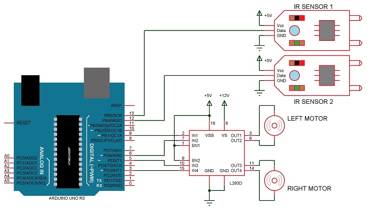
Circuit Diagram
Components Required
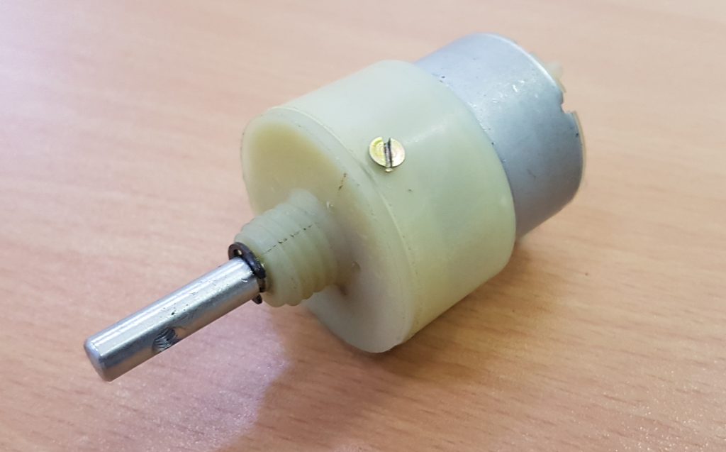
Arduino UNO (or Arduino Nano) [Buy Here] L293D Motor Driver IC [Buy Here] Geared Motors x 2 Robot Chassis IR Sensor Module x 2 Black Tape (Electrical Insulation Tape) Connecting Wires Power supply Battery Connector Battery Holder
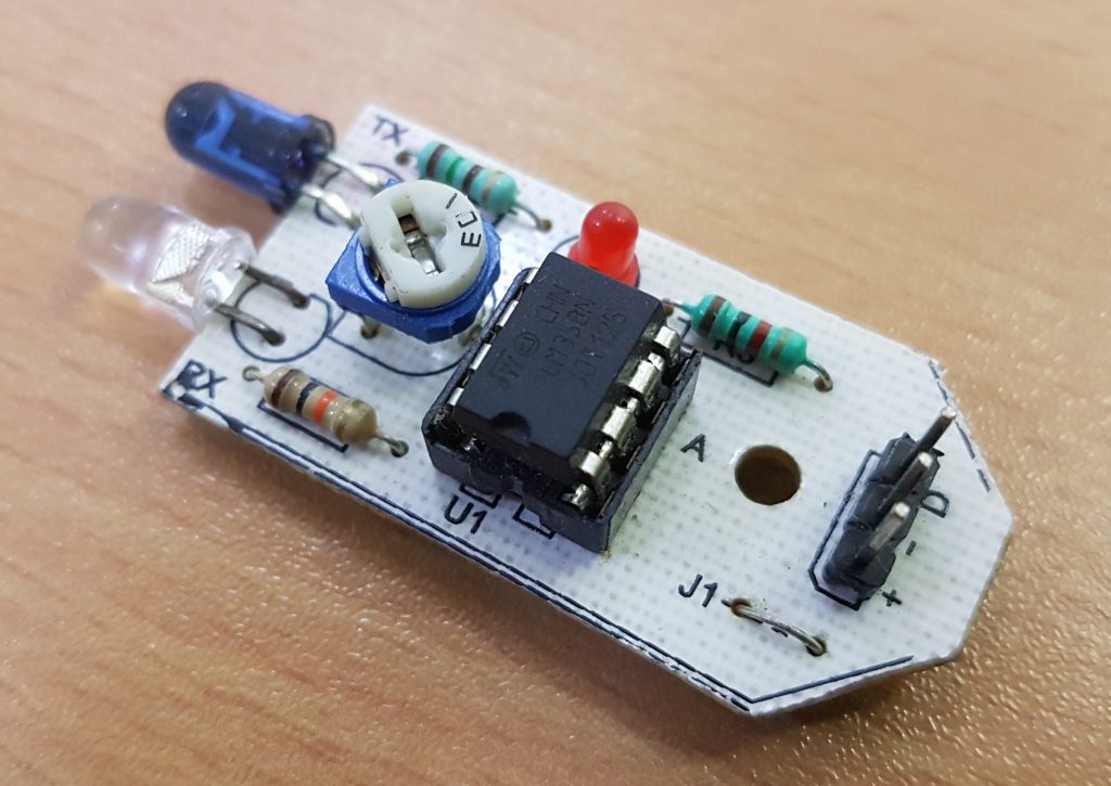
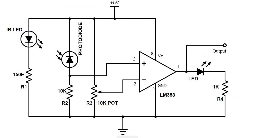
Note: We have used a prebuilt IR Sensor Module that consists of an IR LED and a Photo Diode. If you do not have this, we have explained how to build one yourself.
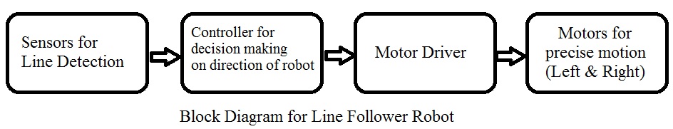
Block Diagram of the Project
The line follower robot built in this project is divided in to 4 blocks. The following image shows the block diagram for line follower robot.
Block Diagram Description
Sensors (IR Sensor): We have used IR Sensor Module as the line detecting sensor for the project. It consists of an IR LED and a Photo diode and some other components like comparator, LED etc.
As mentioned earlier, we have used a pre – assembled IR Sensor. In case you do not have one, you can make your own sensor using the following circuit.
The working of the IR Sensor and its scope in this project will be explained in the actual working of the Line Follower Robot. Controller (Arduino UNO): Arduino UNO is the main controller in the project. The data from the sensors (IR Sensors) will be given to Arduino and it gives corresponding signals to the Motor Driver IC. Motor Driver (L293D): L293D Motor Driver IC is used in this project to drive the motors of the robot. It receives signals from Arduino based on the information from the IR Sensors. Note: The power supply to the motors must be given from the motor driver IC. Hence, choose the appropriate power supply which is sufficient for all the components including the motors. Motors (Geared Motors): We have used two geared motors at the rear of the line follower robot. These motors provide more torque than normal motors and can be used for carrying some load as well.
Working of Arduino Line Follower Robot
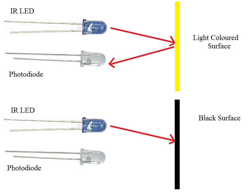
In this project, we have designed an Arduino based Line Follower Robot. The working of the project is pretty simple: detect the black line on the surface and move along that line. The detailed working is explained here. As mentioned in the block diagram, we need sensors to detect the line. For line detection logic, we used two IR Sensors, which consists of IR LED and Photodiode. They are placed in a reflective way i.e. side – by – side so that whenever they come in to proximity of a reflective surface, the light emitted by IR LED will be detected by Photo diode. The following image shows the working of a typical IR Sensor (IR LED – Photodiode pair) in front of a light coloured surface and a black surface. As the reflectance of the light coloured surface is high, the infrared light emitted by IR LED will be maximum reflected and will be detected by the Photodiode.
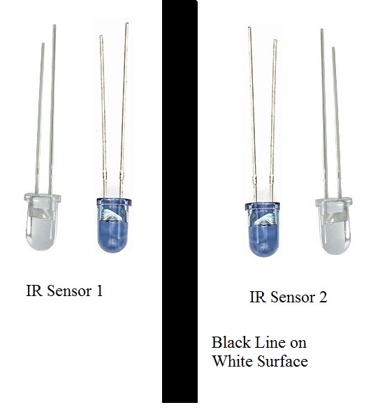
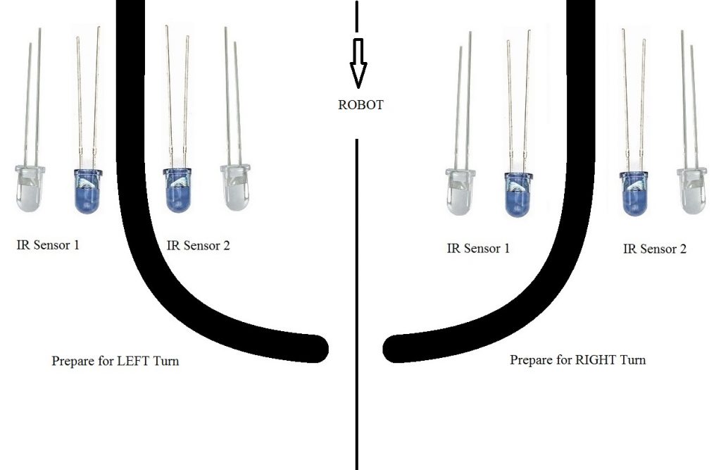
In case of black surface, which has a low reflectance, the light gets completely absorbed by the black surface and doesn’t reach the photodiode. Using the same principle, we will setup the IR Sensors on the Line Follower Robot such that the two IR Sensors are on the either side of the black line on the floor. The setup is shown below.
When the robot moves forward, both the sensors wait for the line to be detected. For example, if the IR Sensor 1 in the above image detects the black line, it means that there is a right curve (or turn) ahead. Arduino UNO detects this change and sends signal to motor driver accordingly. In order to turn right, the motor on the right side of the robot is slowed down using PWM, while the motor on the left side is run at normal speed. Similarly, when the IR Sensor 2 detects the black line first, it means that there is a left curve ahead and the robot has to turn left. For the robot to turn left, the motor on the left side of the robot is slowed down (or can be stopped completely or can be rotated in opposite direction) and the motor on the right side is run at normal speed. Arduino UNO continuously monitors the data from both the sensors and turns the robot as per the line detected by them.
Code
Note:
In order to increase the efficiency of black line detection, number of sensors can be increased. An array of sensors will be more accurate than just two sensors. In this project (where two sensors are used), the positioning of the sensors is very important. The width of the black line plays a major role in the placement of the sensors. The sensor to detect the line can also be constructed using an LED and LDR pair.
Applications of Line Follower Robot
Line follower Robots are commonly used for automation process in industries, military applications and consumer applications. They are very useful as they can work without any supervision i.e. they work as automatic guided vehicles. With additional features like obstacle avoidance and other security measures, line follower robots can be used in driver less cars.
Construction and Output Video
This is the starter kit that has come into the existence when a motion of the robot is given high priority. It follows the visual line path and some advanced line follower robots uses an invisible magnetic field as their paths. As you are aware of robot applications in military, industries and domestic purposes that are in great demand. We offered the Arduino Robot Kits that satisfies all your desires. Have a look at these Arduino robot kits that has a wide range of applications and comes at very low prices. If you have any doubts, please share with us in the comment section given below. We are very happy to respond quickly. Recommended read:
Arduino Starter Kits
ir (infra red) sensors work with either black or white stripes. the difference is that white sends the ir light back and black doesnt, that is on your choice to pragrammit the way you want. Thanks! if yes, could you help me. // connect motor controller pins to Arduino digital pins // Left Motor int enLeft = 5; int in1 = 6; int in2 = 7; // Right Motor int in3 = 8; int in4 = 9; int enRight = 10; //LightSensor int LightRight = 4; int LightLeft = 3; //Ultasound sensor int echoPin = 11; int trigPin =12; double RANGE(); void goMotors(int, int, int, int); void setup() { // set all the motor control pins to outputs pinMode(enLeft, OUTPUT); pinMode(enRight, OUTPUT); pinMode(in1, OUTPUT); pinMode(in2, OUTPUT); pinMode(in3, OUTPUT); pinMode(in4, OUTPUT); pinMode(trigPin, OUTPUT); pinMode(echoPin, INPUT); } void loop() { //The Light Sensor is on if it can sense the reflected light //If the background is black there is no reflection thus it is off //When the background is white there is a reflection this it is on. if(digitalRead(LightRight)==LOW && digitalRead(LightLeft)==LOW) { //If there is black line stop goMotors(enLeft,in1,in2,00); goMotors(enRight,in3,in4,00); } else if (digitalRead(LightRight)==LOW && digitalRead(LightLeft)==HIGH) { //If there is no black line stop goMotors(enLeft,in1,in2,-100); goMotors(enRight,in3,in4,00); } else if (digitalRead(LightRight)==HIGH && digitalRead(LightLeft)==LOW) { goMotors(enLeft,in1,in2,00); goMotors(enRight,in3,in4,-100); } else if(digitalRead(LightRight)==HIGH && digitalRead(LightLeft)==HIGH) { //If there is no black line move goMotors(enLeft,in1,in2,-100); goMotors(enRight,in3,in4,-100); } //Arduino IDE code for Obstacle detecting Robot const int trig = 12; const int echo = 11; long duration, inches, cm; void setup() { Serial.begin(9600); pinMode(trig,OUTPUT); pinMode(echo,INPUT); pinMode(goMotors enLeft, OUTPUT); pinMode(goMotors enRIGHT, OUTPUT); } void loop() { digitalWrite(trig, LOW); delayMicroseconds(2); digitalWrite(trig, HIGH); delayMicroseconds(5); digitalWrite(trig, LOW); duration = pulseIn(echo, HIGH); //this returns the time duration taken //for the ultrasonics to hit an obstacle and return inches = duration / 74 / 2;//converts the time duration into inches cm = duration / 29 / 2;//converts the time duration to cm if(cm>15)//checks for the distance is greater than 15cm //the motor moves forward if the condition is true digitalWrite(goMotors enLeft,HIGH);//Both the motors are moving digitalWrite(goMotors enRight,HIGH); Serial.print(“No obstacle detected”); } else //the robot turns left when an obstacle is detected digitalWrite(goMotors enRight,HIGH);//the right motor is in ON state digitalWrite(goMotors enLeft,LOW);//the left motor is in OFF state Serial.print(“Obstacle detected”); delay(100);//this delays the process by 100milliseconds delay(100);//this delays the code by 0.1 seconds and repeats the loop again } That may be causing the Arduino to not receive any signal in declared pins //Ultasound sensor int echoPin = 11; int trigPin =12; double RANGE(); void goMotors(int, int, int, int); My email nabinsharma74916@gmail.com Comment * Name * Email * Website
Δ
![]()
![]()
![]()

![]()
![]()

