The aim of the article is to develop an auto irrigation system which measures the moisture of the soil and automatically turns on or off the water supply system. The project requires very less human involvement once installed. The circuit is based on PIC microcontroller and also a soil moisture sensor. A properly configured soil moisture sensor can save up to 60 percent of water used in irrigation. The designed system can be used in turf grass or with small garden plants.
Circuit Diagram
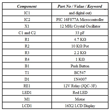
Components Required
Component Description
PIC 16F877A
The microcontroller used in the project is PIC 16F877A. It is an 8-bit microcontroller. The main functions of the microcontroller are reading the values from the soil moisture sensor, displaying appropriate messages on the LCD and controlling the relay to the motor.
Soil Moisture Sensor Module
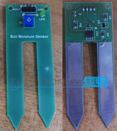
A soil moisture sensor is used to measure the volumetric water content of soil. The sensor used in the project is shown below.
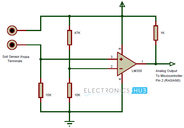
It consists of two prongs, which must be inserted in the soil, an LM358, which acts as a comparator and a pot to change the sensitivity of the sensor. If the soil moisture sensor is not available, the following circuit can be used as an alternative. The circuit shown below has a fixed sensitivity. This can be changed by implementing a pot in place of one of the resistors connected to the non-inverting terminal of the comparator.
Circuit Design of Auto Irrigation System using Soil Moisture Sensor
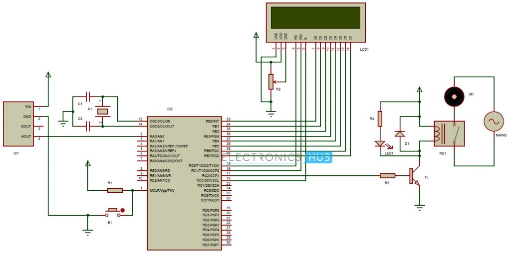
The aim of the project is to control a motor based on the moisture in the soil. The design of the circuit is as follows. PIC 16F877A is the main processing IC. A 12 MHz crystal oscillator is connected across OSC1 and OSC2 (Pins 13 and 14). The crystal is connected with two 33pF capacitors. The Master Clear pins is normally connected to Vcc via a pull-up resistor. A bypass button is connected to ground. This button is used to reset the microcontroller. The output of the soil moisture sensor is given to RA0 (Pin 2) of the PIC microcontroller. An LCD is used to display the key messages. The data pins of the LCD are connected to Port B of the PIC (Pins 33 – 40). The control pins of the LCD are connected to the Port C. The connections are as follows: RS pin of LCD to RC0 (Pin 15) of PIC, RW to RC1 (Pin 16) and E to RC3 (Pin 18). In order to drive the relay which is connected to the motor, a transistor is used. The input to the transistor is given from RC2 (Pin 17) of PIC microcontroller. One terminal of the relay coil is supplied with a 12 V DC. The other end of the coil is connected to the collector of the transistor. The contacts of the relay are given to the motor and AC supply. An LED is connected between the DC supply and the collector and glows only when the motor is running.
Working of the Circuit
The idea of the project is to implement an automatic irrigation system by sensing the moisture of the soil. The working of the circuit is as follows. The soil moisture sensor is inserted in the soil. Depending on the quality of the sensor, it must be inserted near the roots of the plant. The soil moisture sensor measures the conductivity of the soil. Wet soil will be more conductive than dry soil. The soil moisture sensor module has a comparator in it. The voltage from the prongs and the predefined voltage are compared and the output of the comparator is high only when the soil condition is dry. This output from the soil moisture sensor is given to the analogue input pin (Pin 2 – RA0) of the microcontroller. The microcontroller continuously monitors the analogue input pin. When the moisture in the soil is above the threshold, the microcontroller displays a message mentioning the same and the motor is off. When the output from the soil moisture sensor is high i.e. the moisture of the soil is less. This will trigger the microcontroller and displays an appropriate message on the LCD and the output of the microcontroller, which is connected to the base of the transistor is high. When the transistor is turned on, the relay coil gets energized and turns on the motor. The LED is also turned on and acts as an indicator. When the moisture of the soil reaches the threshold value, the output of the soil moisture sensor is low and the motor is turned off. The system is also designed to warn when the moisture is very high than the threshold and the soil is too wet, which is dangerous for the plant.
Applications
The circuit can be used to measure the loss of moisture in the soil over time due to evaporation and intake. Minimizes water waste and improves plant growth. The circuit is designed to work automatically and hence, there is no need for any human intervention. The project is intended for small gardens and residential environment. By using advanced soil moisture sensor, the same circuit can be expanded to large agricultural fields.
[Read : Automatic Plant Irrigation System] Can I use PIC 18F452? Thanks & Regards Comment * Name * Email * Website
Δ


![]()