But why blinking LEDs? Blinking LEDs will be the first practical project , that many implement when starting with a new MCU as it is the “Hello, World!” of the electronics. So, without deviating from the tradition, let us blink some LEDs using ARM7 LPC2148. The aim of this project is to blink a set of LEDs connected to the pins of ARM7 LPC2148 so that we can understand how to configure the registers of the MCU and some other basic functions.
Schematic
Components Required
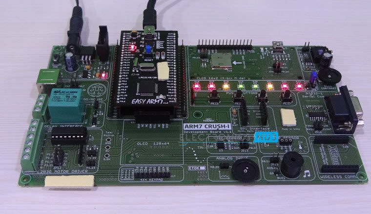
If you have an ARM7 LPC2148 development board, then the board itself consists of few LEDs to test the program. In this case, you don’t need anything other than the development board itself. In case you don’t have a development board or for some reason your development board doesn’t have on – board LEDs, then you might need the following components.
ARM7 LPC2148 based Stand – alone board or ARM7 LPC2148 Development Board LEDs x 8 no’s 1 KΩ Resistors x 8 no’s Power supply Connecting wires USB – to – Mini USB cable
Circuit Design
If you are using a development board, then all the connections are already made on the board. All you need to do is to power – up the board, upload the program to the MCU and see the output. If you have a stand – alone board, which only consists of basic components like crystal, USB – to – UART chip, etc. then you need to make the following connections. Since we intend to blink 8 LEDs, we need to connect 8 LEDs to any GPIO pins along with their current limiting resistors. So, let us connect the LEDs to PORT1 pins i.e. P1.18 to P1.25 with a series resistor of 1 KΩ each. Rest of the connections will be already made on the LPC2148 stand – alone board.
Working of the Project
The working of the project is very simple. Since we want to turn ON and OFF the LEDs , connected to the GPIO pins, all we need to do is to set the respective pins HIGH and LOW with a certain delay so that we get the blinking effect. To set a Pin as HIGH, we need to set “1” on the corresponding pin. Similarly, in order to set a Pin as LOW, we need to set “0” on the corresponding pin. The project can be understood better if we go through the program and understand it.
Code
Understanding the Program
In order to blink the LEDs, we will make use of PLL, Timer and GPIO features of the LPC2148 MCU. So, we will see module by module, how to initialize them and use them in our project. First is the PLL. PLL is used to set the system clock and peripheral clock at user defined value. The following lines of code will help us in initialising the PLL and also setting up the System clock (CCLK) and Peripheral clock (PCLK) at 60 MHz respectively. Detailed information of the PLL module and its registers are explained in the PLL Tutorial.
PLL0CON = 0x01; // PLL0 is enabled but not connected PLL0CFG = 0x24; // The Multiplier and the Divider values are set to get the clock as 60 MHz PLL0FEED = 0xAA; // Feed sequence is set for locking the PLL0 to the specified frequency. PLL0FEED = 0x55; while (! (PLL0STAT & PLOCK)); // Checking for Lock status of the PLL PLL0CON = 0x03; // PLL0 is connected PLL0FEED = 0xAA; // Feed sequence for setting the PLL0 as System Clock PLL0FEED = 0x55; VPBDIV = 0x01; // Peripheral clock is set as system clock The next module is the Timer. We will initialize the timer and also use a delay function to generate a time delay. First, we will see how to initialize the timer in LPC2148. For that, we need to follow the following commands. T0CTCR=0x00; // Select the Timer Mode in Timer0. T0PR=59999; // For TC to increment after every 1 ms, PR is set to this value. T0TCR=0x02; // Timer is Reset
The next task is to generate a delay between the blinking of the LED. For that, we will use the Timer module and define a delay function. In order to generate a delay of “d” milliseconds, the following function can be used. void delay (int d) { T0TCR=0x02; // Timer is Reset T0TCR=0x01; // Timer is Enabled While (T0TC < d); // TC is incremented till the desired delay is reached T0TCR=0x00; // Timer is disabled. } More information about Timers in LPC2148 is in Timers Tutorial. The next part of the program is related to the input / output function of the pins. By default, all the Pins are set as GPIO. If we want to manually set a pin as GPIO, we can do it using the PINSEL register. We have already seen in the ARM GPIO Introduction tutorial how to initialize a particular pin of the LPC2148 MCU as a GPIO pin. Since the LEDs are connected to PORT1 pins, we need to use PINSEL2 register to configure them as GPIO. PINSEL2 = 0x00; // All the user accessible pins in PORT1 are set as GPIO. Next, we need to set the direction of the pins i.e. either Input or Output. For this, we use IODIR register. Set the PORT1 pins as Outputs as we need to control the LEDs. IODIR1 = 0xFFFFFFFF; // All the pins of the PORT1 are set as Outputs. After setting the Pins as Outputs, the final step is to Blink the LEDs. For this, we need to turn ON the LEDs by setting “1” on the pins using IOSET register, give a delay of 1000 ms, turn OFF the LEDs by setting “0” on the pins using IOCLR register and then give another delay of 1000 ms. The process is repeated until the system is powered down. IOSET1=0xFFFFFFFF; delay (1000); IOCLR1=0xFFFFFFFF; delay (1000); Comment * Name * Email * Website
Δ
![]()
![]()
![]()


![]()
![]()

