These are employed for applications for which a greater stability is required, i.e., accurately maintaining an exact frequency of oscillations such as watches, communication transmitter and receivers. In LC oscillators the frequency is determined by the inductance and capacitance values. But such variables can change with climate, time and temperature fluctuations. Therefore, LC oscillators are not suitable for frequency stability applications. But in case of crystal oscillator, crystal is a frequency-determining element which offers a high frequency stability.
What is a Quartz Crystal?
The crystals are either synthetically manufactured or naturally occurring elements which exhibits the piezoelectric effect. Piezoelectric effect is an electromechanical phenomenon which causes to develop a potential difference across the opposite faces of the crystal whenever a mechanical pressure is applied across one set of its faces. Therefore an AC voltage gets generated across the crystal whenever force causes the crystal to vibrate. Conversely, when an alternating voltage is applied to crystal, mechanical vibrations are setup causing mechanical distortion in the crystal shape. These vibrations or oscillations oscillate at resonant frequency which is determined by the crystal’s cut and physical size.
This is because every crystal has its own resonant frequency depending on its cut. Therefore, it generates constant frequency signal under the influence of mechanical vibrations. A thin slice of quartz in a hermetically sealed enclosure with symbolic representation is given in above figure. Basically, it is in the shape of hexagonal with pyramids at ends. But, it is cut down to the rectangular slab slices for its practical usage. The process involved in cuts include X cut, Y cut, AT cut and so on. And then this slab is mounted between two metal plates. These metal plates are called as holding plates because they hold crystal slab in between them. Crystals are available from few KHz to few MHz and quality factor from several thousands to hundreds of thousands. These high values of quality factor make the crystal extremely stable with respect to temperature and time.
Equivalent Circuit of Quartz Crystal
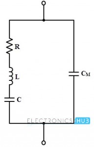
When the crystal is steady i.e., not vibrating then the crystal is equivalent to a capacitance due to its mechanical mounting. This capacitance is called as mounting capacitance CM which exists between two metal plates separated by a dielectric as crystal slab. This CM is a shunt capacitance. When the crystal starts vibrating, there will be internal friction losses which are denoted by the resistance R, while crystal has some mass , so its inertia is represented by an inductance L. During the vibrating condition, crystal exhibits some stiffness which is denoted by the capacitor C. Therefore, three elements R, L, and C are the characteristics of the natural crystal whereas the CM is the capacitance of the electrodes supporting the crystal. All these values are determined by the crystal cut, its size and nature of the vibrations. The overall equivalent circuit of the crystal is shown below.
These RLC parameters forms the resonant circuit and the resonant frequency expressed as, fr = (1/ (2π √ (LC))) √ (Q2 / (1 + Q2)) Where Q is the quality factor and its value is equal to 2 π f L / R. The value of the Q of a crystal is very high and is typically 20000. And hence the factor √ (Q2 / (1 + Q2) becomes unity. Then the resonating frequency is fr = (1/ (2π √ (LC)) In fact the crystal frequency is inversely proportional to the thickness. Therefore the thickness should be very small in order to have very high frequencies. But, there will be a possibility of crystals getting damaged under vibrations. Thus, the crystal oscillators are used for the frequency range from about 200 or 300 KHz.
Series and Parallel Resonance
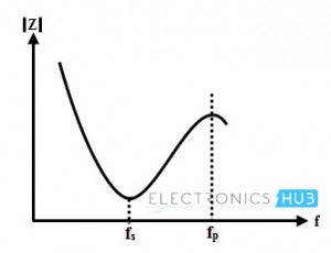
From the equivalent circuit of the crystal oscillator, it can be seen that the circuit has two resonant frequencies namely series and parallel resonating frequencies. Series resonance occurs when the reactance of the series RLC leg are equal, i.e., XC = XL. At the series resonating frequency, the reactance of series LC arm is zero and the impedance offered by this branch is R alone under the series resonance. This series resonating frequency is expressed as fs = (1/ (2π √ (LC)) When the reactance of the series resonant leg equals to the reactance of the mounting capacitor, then the parallel resonant condition occurs. The reactance of the series arm is inductive at the frequencies greater than fs. The impedance offered by the crystal to the external circuit is very high under this resonance condition. The equivalent capacitance under parallel resonance is Ceq = CM C/ CM+ C The parallel resonating frequency is given by fp = (1/ (2π √ (LCeq)) The figure below shows the relationship between crystal impedance and frequency when the value of the capacitance in series leg is much smaller than CM.
Generally, fp and fs are very close to each other and therefore practically it is said that only one resonating frequency exist for a crystal.
Colpitts Crystal Oscillator
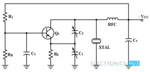
Colpitts crystal oscillator is used primarily at the high radio frequencies as a stable oscillator which uses a quartz crystal to control the oscillator frequency. Feedback is provided through a capacitive voltage divider arrangement which is usually external but it may be provided through capacitor elements. The figure below shows a common-emitter Colpitts circuit using external capacitive feedback method.
In the above circuit the voltage divider bias is provided by the R1 and RB resistor for easy starting and C3 is a bypass capacitor which effectively isolates the base from RF variations. Capacitors C1 and 2 are connected between collector and emitter for feedback purpose. The adjustment and control of the feedback is provided by these two variable capacitors. Crystal is connected between the collector and ground and operates as a parallel resonant circuit. The collector is supplied through RFC in conjunction with C4 which serves as power supply isolation circuit. The output may be taken capacitively at the collector terminal.
Operation
The operation of this crystal oscillator depends on the action of voltage divider circuit which consists of capacitors C1 and C2. When the power is applied to the circuit, a small bias current is flows through RB. Then the collector current flows and a voltage appear across the capacitor divider.
Assume that noise pulse occurring within the transistor causes to increase the collector current. This will cause collector voltage to decrease and the capacitor C2 couples this voltage change to the emitter. The decreasing negative signal (positive going) applied to the emitter is regenerative. This will cause a further increase in collector current. The collector voltage continues to decrease (a negative voltage changing in a positive direction) and the capacitor C2 continues to couple this charging voltage to the emitter. At the same time, the change in collector voltage appears across the crystal. Thus the crystal is slightly strained mechanically by the piezoelectric action. When the collector current reaches the saturation level no further change occurs and the regenerative action ceases. At this time the electrostatic strain across the crystal begins to decrease and the capacitor C1 begins a slight discharge through RE, finally the collector current starts to fall. This action is also regenerative and the transistor quickly comes into the cut-off mode. As the collector current decreases, the collector voltage increases (more negative) and now the crystal stresses in the opposite direction. Therefore, for each cycle of this action continues, the crystal oscillates at its parallel resonant frequency. Since oscillations of the crystal produces a voltage across it, once started into vibration the crystal will continue to oscillate. Since the crystal is connected in shunt from the collector to ground, it effectively functions as a parallel resonant circuit and smooths out the pulses of oscillations into approximate sine waveforms.
It is also possible to design the crystal oscillator with a variety of circuit configurations. The most common types of other circuit arrangements include Miller crystal oscillators and Pierce crystal oscillators.
Microprocessor Crystal Clocks
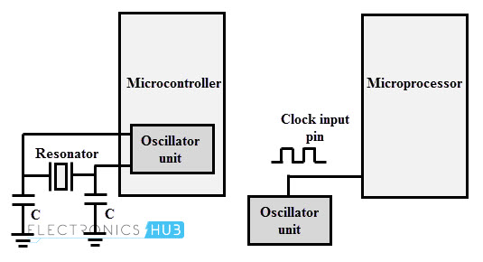
As we have discussed that crystal oscillators are used to produce the oscillation with higher frequency stability. This is the reason why the crystal oscillators are used in digital systems for generating clock signal. Since the instruction execution of microprocessor or controller takes place in sync with a clock signal. Certain type of controllers has in-built oscillator circuit and they require only a quartz crystal to produce the necessary clock signals. Certain digital devices may not contain built-in oscillator unit and hence they need external oscillator circuit so that clock pulses are generated from it.
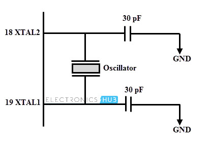
The above figure shows the usage of quartz crystal oscillator for microprocessor clock frequency generation and in case of microcontroller a quartz crystal resonator is enough to do the job. Depending on the value of maximum clock frequency at which system can run, the oscillator circuit or the value of crystal is decided. The below figure illustrates 8051 microcontroller which operates based on an external crystal oscillator. Very often a quartz crystal oscillator is connected between the input pins XTAL1 and XTAL2. XTAL1 is the input to the inverting oscillator amplifier and input to the internal clock generating circuits whereas XTAL2 is output from the inverting oscillator amplifier. In case of 8052 microcontroller, most commonly used crystal frequencies are 12 megahertz and 11.059 megahertz, however 11.059 being much more common.
Example problem
A quartz crystal has the following parameter: CM = 1 pF, R= 5K ohms, L = 0.4 H and C= 0.085pF. Then find series resonant frequency, parallel resonant frequency and quality factor of the crystal. From the above discussed parallel and series resonant concept, the series resonating frequency is expressed as fs = (1/ (2π √ (LC)) = (1/ (2π √ (0.4 × 0.085 × 10-12)) = 0.856 MHz The parallel resonating frequency is given by fp = (1/ (2π √ (LCeq)) The equivalent capacitance under parallel resonance is Ceq = CM C/ CM + C = (0.085 × 1) / (0.085 + 1) = 0.078 pF fp = (1/ (2π √ (LC)) = (1/ (2π √ (0.4 × 0.078 × 10-12)) = 0.899 MHz The quality factor Q = ws L / R = 2π fs L / R = (2π × 0.856 × 106 × 0.4) / 5 × 103 = 430.272
Comment * Name * Email * Website
Δ




![]()