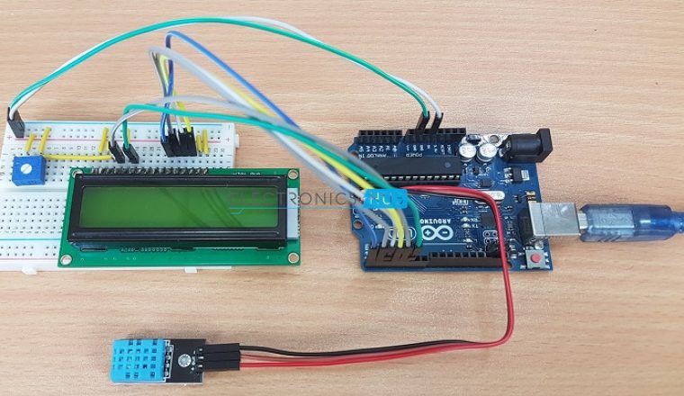
In this project, we will build a small circuit to interface Arduino with DHT11 Temperature and Humidity Sensor. One of the main applications of connecting DTH11 sensor with Arduino is weather monitoring. We have already seen about humidity, relative humidity, humidity sensors and their types in this article.
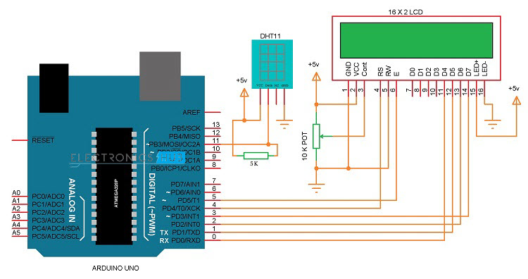
Circuit Diagram
The following circuit diagram shows all the necessary connections required to implement this project.
Components Required
Arduino UNO [Buy Here] DHT11 Temperature and Humidity Sensor Breadboard (or perfboard) Power supply 16 x 2 LCD Display [Buy Here] 10K Ohm Potentiometer 5K Ohm Resistor (1/4 W) Connecting wires
Circuit Description
We will see the circuit design of DHT11 interfacing with Arduino. The DHT11 Humidity and Temperature sensor comes in two variants: just the sensor or a module. The main difference is that the module consists of the pull – up resistor and may also include a power on LED. We have used a module in this project and if you wish to use the sensor itself, you need to connect a 5K Ω pull – up resistor additionally. Coming to the design, the data pin of the DHT11 Sensor is connected to the Pin 11 of Arduino. A 16 x 2 LCD display is used to display the results. The control pins of LCD i.e. RS and E (Pins 4 and 6 on LCD) are connected to pins 4 and 5 of Arduino. The data pins of LCD i.e. D4 to D7 (pins 11 to 14 on LCD) are connected to pins 0 to 3 on LCD. NOTE: For ease of connection, we have connected the DHT11 Sensor Module at the ICSP pins of the Arduino as it provides adjacent VCC, DATA and GND pins. This type of connection is not necessary and you can connect the data pin of sensor to normal Digital I/O pins.
Component Description
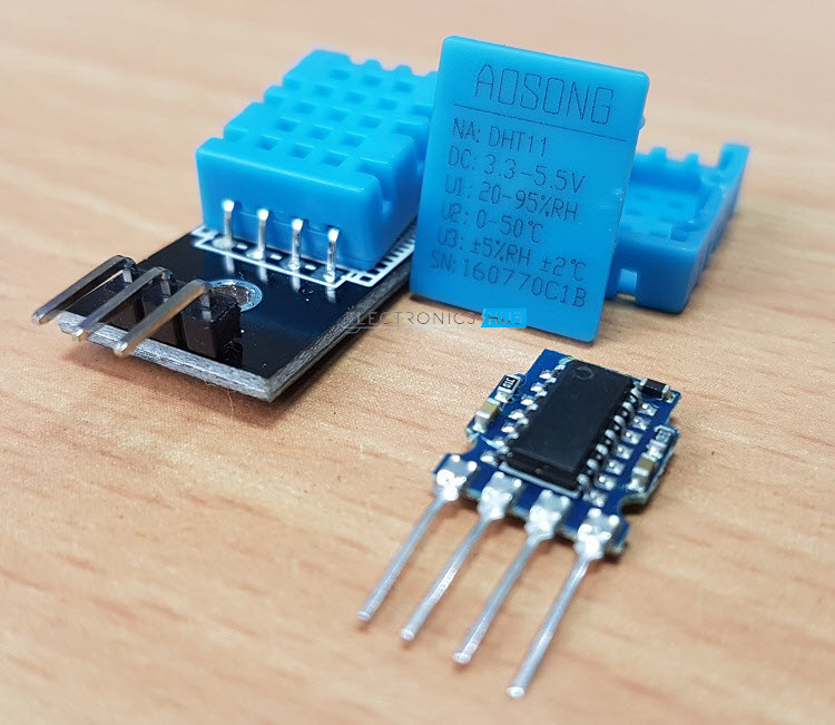
DHT11 Temperature and Humidity Sensor
DHT11 is a part of DHTXX series of Humidity sensors. The other sensor in this series is DHT22. Both these sensors are Relative Humidity (RH) Sensor. As a result, they will measure both the humidity and temperature. Although DHT11 Humidity Sensors are cheap and slow, they are very popular among hobbyists and beginners.
The DHT11 Humidity and Temperature Sensor consists of 3 main components. A resistive type humidity sensor, an NTC (negative temperature coefficient) thermistor (to measure the temperature) and an 8-bit microcontroller, which converts the analog signals from both the sensors and sends out single digital signal. This digital signal can be read by any microcontroller or microprocessor for further analysis.
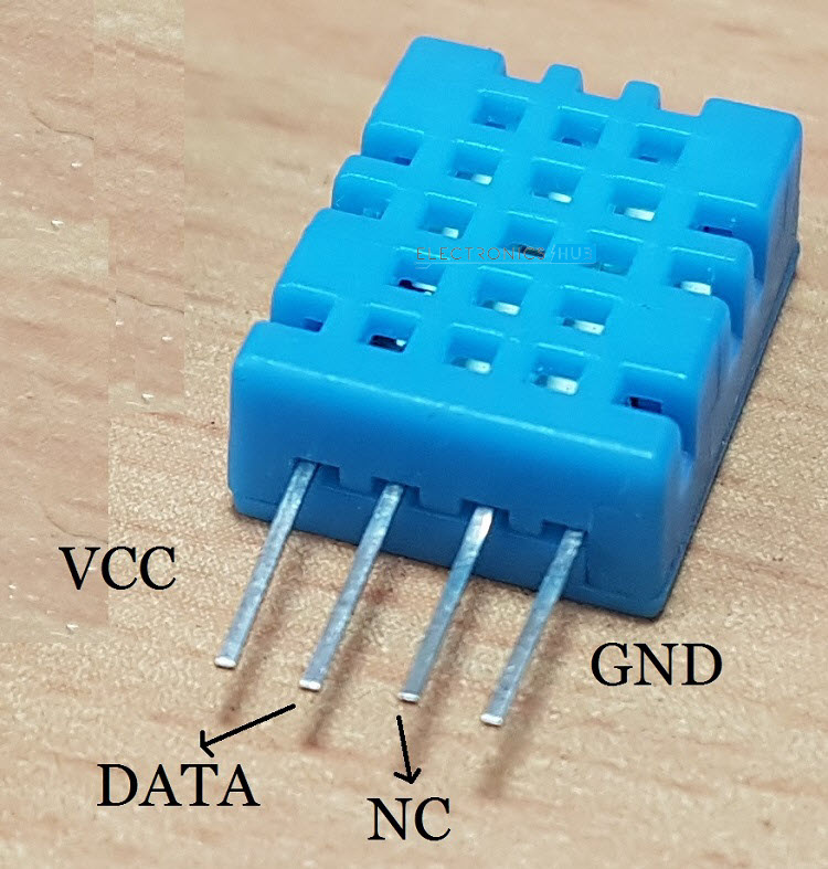
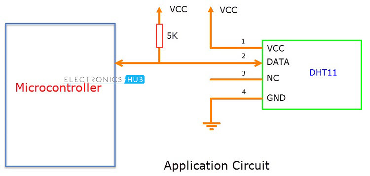
DHT11 Humidity Sensor consists of 4 pins: VCC, Data Out, Not Connected (NC) and GND. The range of voltage for VCC pin is 3.5V to 5.5V. A 5V supply would do fine. The data from the Data Out pin is a serial digital data. The following image shows a typical application circuit for DHT11 Humidity and Temperature Sensor. DHT11 Sensor can measure a humidity value in the range of 20 – 90% of Relative Humidity (RH) and a temperature in the range of 0 – 500C. The sampling period of the sensor is 1 second i.e. All the DHT11 Sensors are accurately calibrated in the laboratory and the results are stored in the memory. A single wire communication can be established between any microcontroller like Arduino and the DHT11 Sensor. Also, the length of the cable can be as long as 20 meters. The data from the sensor consists of integral and decimal parts for both Relative Humidity (RH) and temperature. The data from the DHT11 sensor consists of 40 – bits and the format is as follows: 8 – Bit data for integral RH value, 8 – Bit data for decimal RH value, 8 – Bit data for integral Temperature value, 8 – Bit data for integral Temperature value and 8 – Bit data for checksum.
Example
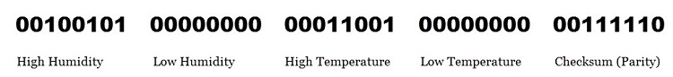
Consider the data received from the DHT11 Sensor is 00100101 00000000 00011001 00000000 00111110. This data can be separated based on the above mentioned structure as follows In order to check whether the received data is correct or not, we need to perform a small calculation. Add all the integral and decimals values of RH and Temperature and check whether the sum is equal to the checksum value i.e. the last 8 – bit data. 00100101 + 00000000 + 00011001 + 00000000 = 00111110 This value is same as checksum and hence the received data is valid. Now to get the RH and Temperature values, just convert the binary data to decimal data. RH = Decimal of 00100101 = 37% Temperature = Decimal of 00011001 = 250C
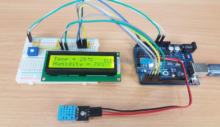
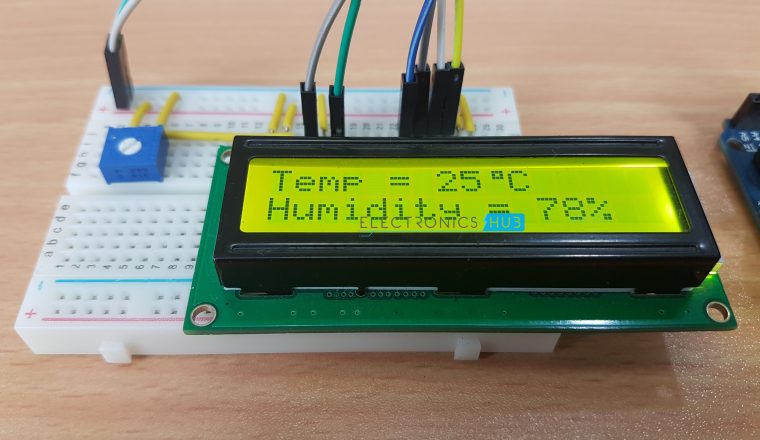
Working of the Project
A simple project is built using Arduino UNO and DHT11 Humidity and Temperature Sensor, where the Humidity and Temperature of the surroundings are displayed on an LCD display. After making the connections, we need not do anything as the program will take care of everything. Although there is a special library for the DHT11 module called “DHT”, we didn’t use it. If you want to use this library, you need to download this library separately and add it to the existing libraries of Arduino. The program written is based on the data timing diagrams provided in the datasheet. The program will make the Arduino to automatically read the data from the sensor and display it as Humidity and Temperature on the LCD Display.
CODE
Applications
DHT11 Relative Humidity and Temperature Sensor can be used in many applications like: HVAC (Heating, Ventilation and Air Conditioning) Systems Weather Stations Medical Equipment for measuring humidity Home Automation Systems Automotive and other weather control applications
Construction and Output Video
Recommended read:
Arduino Starter Kits
#include LiquidCrystal lcd(4, 5, 0, 1, 2, 3); byte degree_symbol[8] = { 0b00111, 0b00101, 0b00111, 0b00000, 0b00000, 0b00000, 0b00000, 0b00000 }; int gate=11; volatile unsigned long duration=0; unsigned char i[5]; unsigned int j[40]; unsigned char value=0; unsigned answer=0; int z=0; int b=1; void setup() { lcd.begin(16, 2); lcd.print(“Temp = “); lcd.setCursor(0,1); lcd.print(“Humidity = “); lcd.createChar(1, degree_symbol); lcd.setCursor(9,0); lcd.write(1); lcd.print(“C”); lcd.setCursor(13,1); lcd.print(“%”); } void loop() { delay(1000); while(1) { delay(1000); pinMode(gate,OUTPUT); digitalWrite(gate,LOW); delay(20); digitalWrite(gate,HIGH); pinMode(gate,INPUT_PULLUP);//by default it will become high due to internal pull up // delayMicroseconds(40); duration=pulseIn(gate, LOW); if(duration = 72) { while(1) { duration=pulseIn(gate, HIGH); if(duration = 20){ value=0;} else if(duration = 65){ value=1;} else if(z==40){ break;} i[z/8]|=value«(7- (z%8)); j[z]=value; z++; } } answer=i[0]+i[1]+i[2]+i[3]; if(answer==i[4] && answer!=0) { lcd.setCursor(7,0); lcd.print(i[2]); lcd.setCursor(11,1); lcd.print(i[0]); } z=0; i[0]=i[1]=i[2]=i[3]=i[4]=0; } } Just a beginner here on arduino. Any suggestion? Comment * Name * Email * Website
Δ
![]()
![]()
![]()

![]()
![]()

