GSM Interfacing with 8051 Microcontroller Circuit Principle:
The main principle of this circuit is to interface a GSM modem with the microcontroller. The microcontroller used is AT89C51 microcontroller. To communicate with GSM modem, AT commands are required. Microcontroller sends these commands to the GSM modem, which is then activated to perform the required operation. The following AT commands are frequently used to control the operations of GSM modem. Command – Operation AT+CSMS – Select message service. AT+CMGF – Message format. AT+CMGL – List messages. AT+CMGR – Read message. AT+CMGS – Send message. AT+CMGD – Delete message. ATA – Answer a call. ATD – Dial a number. ATDL – Dial the last outgoing number. ATH – Hang up the call.
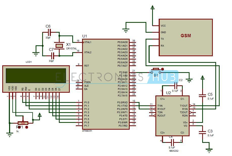
GSM Modem Interfacing with 8051 Microcontroller Circuit Diagram:
Circuit Components:
MAX232 IC. AT89C51 microcontroller. GSM modem. Capacitors C1, C2, C3, C4, C5, C6. Crystal oscillator. Liquid crystal display. Potentiometer.
Circuit Design of Interfacing of GSM Modem to AT89C51 Microcontroller:
The circuit of interfacing GSM to AT89C51 microcontroller mainly consists of GSM modem and 8051 family microcontroller. GSM has RS232 interface for serial communication. In between the GSM module and the microcontroller MAX232 IC is connected. MAX232 IC is used for converting the logic levels. RS232 logic levels of GSM are converted to the TTL logic levels of the microcontroller using this MAX232 IC. MAX232 IC has 16 pins. This is a dual driver IC as it has two transmitters and receivers. Interfacing of GSM to AT89C51 microcontroller uses only one transmitter and receiver. The transmitter pin T1IN of max232 is connected to the transmitter pin of the microcontroller. The receiver pin R1out of the max232 is connected to the receiver pin of the microcontroller. The T1out pin of the IC is connected to the transmitter pin of the GSM modem. The R1IN pin of the IC is connected to the receiver pin of the GSM modem. Two 0.1 micro farad capacitors are connected to the pins of 1, 2 and 4 , 5. Another 1uf capacitor is grounded from pin6 and another capacitor is connected to the supply of 5v from the through the 2nd pin of the IC. GSM modem used here has sim300 module. These wireless modems communicate with the microcontrollers and other devices. This has 4 pins compatible to TTL logic. These can be directly connected to the microcontroller as it has max232 or use the DB9 connector to connect to the controller. In this article, MAX232 pins are connected to the GSM modem. This should be connected to the power supply of 5v. It has a sim slot similar to a mobile to communicate with the network. GSM modem requires AT commands for activation. GSM modem responds to the AT command. An LCD module is connected to the port2 of the microcontroller. This article also shows the interfacing of 4-bit LCD module to the microcontroller. Data bits D4-D7 of the LCD module are connected to the port2 of the microcontroller. A pot is connected to the LCD to adjust the intensity of the display. Here LCD is used for displaying the received message. A button is connected to the PORTB of the microcontroller. This button is used for sending a message.
GSM Interfacing with 8051 Microcontroller Circuit Simulation Video:
DOWNLOAD PROJECT CODE
How to Operate GSM Interfacing with 8051 Microcontroller Circuit?
Initially, connect the circuit as shown in the circuit 8051 Microcontroller diagram. Switch on the power supply. Now send a message from any other phone to the SIM present in the GSM module. Whenever a message is received by the GSM, it is displayed on the LCD. If you want to send a message press the button B1 connected to port B. This sends a message written in the code.
GSM Interfacing 8051 Microcontroller Project Output Video:
GSM Modem Interfacing with 8051 Circuit Applications:
This can be used in automatic accident detection and indication along with GPS. This can also be used to control a robot. This can also be used in GSM based telemedicine system. ATM theft precaution system uses this to indicate the theft. GSM based voting system uses this application. GSM based vehicle security system uses this. This circuit can be used in GSM based green house parameter monitoring system
Although GSM has many advantages there are some limitations. This cannot be used in applications where immediate result is required as it may not work if there are no signals. I am not trying to make something similar. I am trying to make an automatic railway gate control where a user will just send a message via gsm and the gates open or close using a microcontroller. m not trying to make a same project… I want to merge 2 3 applications based on gsm and make a gsm based automated project… it may b home automation type or general applications type… kindly mail me the codes.. thank u… kindly mail me the codes.. thank u… THANK YOU Comment * Name * Email * Website
Δ
![]()
![]()
![]()
![]()
![]()

