What is PWM?
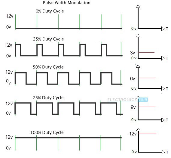
PWM, short for Pulse Width Modulation, is an important concept in modern electronics. It is generally used as a power delivery mechanism in motor control and lighting control systems. In the PWM technique, the voltage that must be supplied to a DC Motor or an LED is supplied in the form fast switching pulses rather than a continuous analog signal. The “Duty Cycle” and the “Frequency” of the PWM Signal determines the output voltage. Duty Cycle of a PWM Signal describes the amount of time the pulse stays HIGH in one cycle. It is usually represented as percentage. If THIGH is the duration for which the pulse is HIGH in one cycle and TLOW is the duration for which the pulse is LOW, then period of the pulse is T = THIGH + TLOW Duty Cycle = (THIGH / T) * 100 Frequency of the PWM Signal describes the rate at which the signal completes one cycle.
The above image shows different PWM Signals and different Duty Cycles along with the output voltage. It is vey easy to generate a PWM Signal using 555 Timer IC. But before seeing how 555 Timer PWM signal is generated, you need to understand the Astable Multivibrator operation of 555 Timer IC. Once you understand this, then by making small modifications, you can effortlessly produce a PWM signal using 555 Timer.
How 555 Timer Works in Astable Mode?
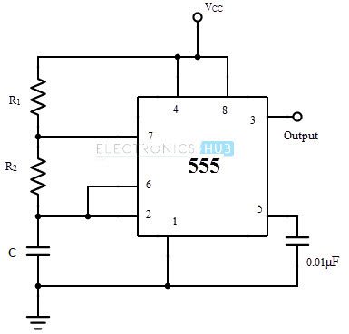
As the name suggests, an Astable Multivibrator is an oscillating circuit without a stable state i.e., it automatically switches between the two states. Hence, an Astable Multivibrator is also known as Free Running Multivibrator or Free Running Oscillator. Using just additional three components, we can make the 555 Timer to work in Astable Mode. They are a couple of resistors and a capacitor.
555 Timer Astable Mode Circuit Diagram
The following image shows a simplified circuit of 555 Timer IC in Astable Mode.
Operation
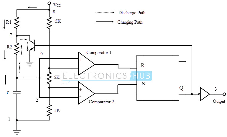
I made a dedicated tutorial on “Astable Multivibrator using 555 Timer”. For detailed explanation, check it out. To understand the working of the 555 Timer in Astable Mode, take a look at the internal circuit of 555 Timer.
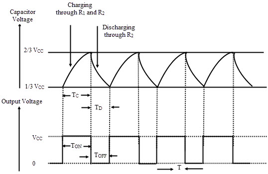
Initially, when the 555 Timer IC is reset, its output is LOW. This will turn ON the internal transistor, which will provide a discharge path for the Capacitor through R2. As the capacitor voltage drops below 1/3 VCC, the output becomes HIGH and transistor is turned OFF. This will make the capacitor to charge through R1 and R2. As the capacitor voltage rises above 2/3 VCC, the output becomes LOW and the cycle continues. The following image shows the relationship between the capacitor voltage and the output voltage.
Essentially, the values of R1, R2 and C will determine the duration for which the output is HIGH or LOW.
Duty Cycle
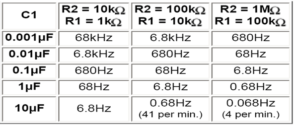
I guess you can understand where we are headed with the above explanation. Since the duration of output being HIGH or LOW is dependent on the charging and discharging times of the capacitor, we can control the duty cycle and the frequency of the output pulse. In the “Astable Mode” tutorial, I derived all the timing and frequency related values. I will just write the final values here. TON = 0.693 * (R1 + R2) * C TOFF = 0.693 * R2 x C Period T = TON + TOFF = 0.693 * (R1 +2*R2) * C Frequency F = 1/T = 1.44 / ( (R1 + 2R2) * C) Hz The following table shows some of the common values for R1, R2 and C and the corresponding frequency.
555 Timer PWM Generation
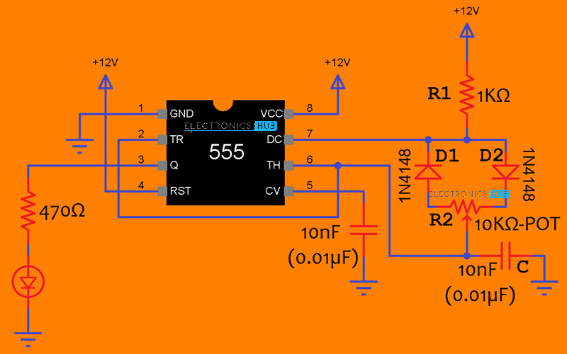
From the above circuit diagram of 555 Timer in Astable Mode, it is clear that the Capacitor is charging through R1 and R2 while it is discharging only through R2. Hence, if we replace R2 with a Potentiometer, we can control the charging and discharging tines of the capacitor and essentially the duty cycle of the PWM Signal. I chose R1 as 1 KΩ resistor, R2 as a 10 KΩ Potentiometer and C as 10nF (0.01µF) Capacitor. Additionally, I added two fast switching diodes, one in the charging path and the other in the discharge path.
Circuit Diagram
The following image shows the circuit diagram of 555 Timer PWM Generation.
Components Required
555 Timer IC 1 KΩ Resistor 10 KΩ Potentiometer 10nF (0.01µF) Capacitor x 2 1N4148 Fast Switching Diode x 2 470Ω Resistor LED Breadboard 12V Power Supply Connecting Wires
Working of 555 Timer PWM Generation
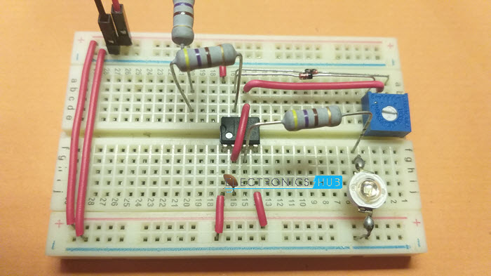
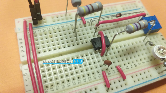
NOTE: Instead of 1 KΩ Resistor for R1, I connected two 470Ω Resistors in series. Also, I did not connect the 10nF capacitor between Pin 5 of 555 IC and GND.
Before understanding the working of 555 Timer PWM Generation Circuit, if you want to calculate the Duty Cycle and Frequency of the PWM Signal based on the chosen components, you can use the aforementioned formulas. Now proceeding with working, the capacitor charges through R1, D2 and right side of R2 and discharges through left side of R2 and D1. So, as we slide the potentiometer’s wiper, we are controlling the charging and discharging times of the capacitor. Since the charging and discharging of capacitor is directly associated with the ON and OFF duration of the output pulse, we can easily vary the duty cycle of the PWM Signal.
Conclusion
A simple project for generating PWM Signal using 555 Timer IC is demonstrated here. To show the outcome, I used an LED as the output device. You can easily modify the above circuit to control the speed of a DC Motor. Comment * Name * Email * Website
Δ




![]()