Now a days, smoke detectors and smoke alarms are very cheap as its usage is increasing and cost of manufacturing is decreasing. In this project, we are implementing a simple Smoke Detector Circuit using simple hardware. We used a Gas/Smoke sensor for detecting smoke. The article is divided into information about Smoke sensor, circuit diagram and working.
A Brief Introduction to Smoke Sensor
There are two types of smoke detectors. Optical or Photoelectric smoke detectors and Ionization smoke detectors. Optical smoke detectors consists of a light source like LED and a light detector like photocell. The photocell conducts as long as the light falls on it. When there is smoke, the light from the source is interrupted and the photocell doesn’t conduct. Ionization smoke detectors consists of two electrodes and an ionization chamber filled with ions. When there is no smoke, the ions move freely and the electrodes conduct normally. In the presence of smoke, the chamber is filled with smoke and interrupts the movement of ions. The electrodes do not conduct anymore. Depending on the type of sensor and manufacturer, the conductivity conditions may change but the idea remains the same. Based on the output of the smoke detector, an alarm system can be implemented. The sensor used in this project is MQ-2 Gas/Smoke sensor. It is sensitive to LPG, Hydrogen, Smoke, Methane, Propane, Alcohol, Butane and other industrial combustible gases. It has two electrodes made of Aluminum Oxide (Al2O3) and a heating element made of Tin dioxide (SnO¬2) which acts as the main sensing layer.
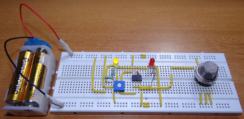
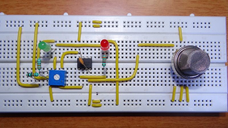
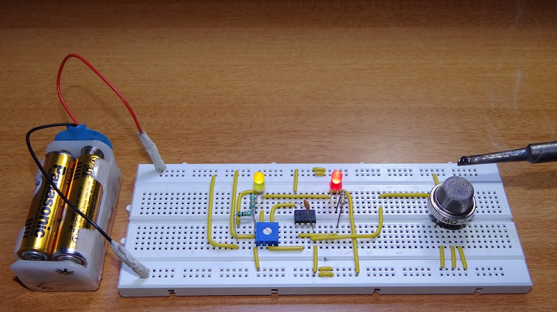
Circuit Diagram
Components Required
MQ-2 Sensor LM358 10KΩ 330Ω LED 0.1µF 10KΩ POT
Working
Smoke Detectors are amazing devices as they are small, cheap yet very useful. In this project, we implemented a simple Smoke Detector Circuit with adjustable sensitivity. We used a Smoke Sensor MQ-2 as the main sensory device. The working of the circuit is simple and is explained below. LM358 acts as a comparator in this circuit. The inverting terminal of LM358 is connected to POT so that the sensitivity of the circuit can be adjusted. The output of LM358 is given to an LED as an indicator although a buzzer can be used as an alarm. The non-inverting terminal of LM358 is connected with output of smoke sensor. Initially, when the air is clean, the conductivity between the electrodes is less, as the resistance is in the order of 50KΩ. The inverting terminal input of comparator is higher than the non-inverting terminal input. The indicator LED is OFF. In the event of fire, when the sensor is filled with smoke, the resistance of the sensor falls to 5KΩ and the conductivity between the electrodes increases. This provides a higher input at the non-inverting terminal of comparator than the inverting terminal and the output of comparator is high. The alarming LED is turned ON as an indication of presence of smoke.
Note
The heating element in the Smoke Sensor must be preheated before it can sense any smoke or gas. The sensor gets hot because of the heating coil and it is advised not to touch the sensor while it is switched on. The sensitivity of the circuit to different concentrations of smoke can be adjusted by using the POT. The output LED can be replaced with a loud buzzer for effective alarm.
shreyasnatraj97@gmail.com Comment * Name * Email * Website
Δ
![]()
![]()
![]()


![]()
![]()

