Generally, you can see various implementations like Automobile DRLs (Daytime Running Lights), decorating houses, regular lamps, emergency lights etc. One such important application is where the LED lights increase and decrease their intensity depending on the number of persons entering or leaving at a particular place or a room. This concept is called Fading of LEDs. Here is a simple circuit where an LED slowly fades out when it is applied with some voltage.
Up Down Fading LED Lights Circuit Principle
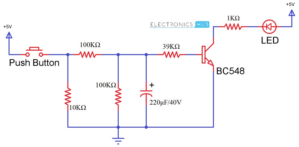
The circuit mainly consists of a transistor and a capacitor. Light Emitting Diode conducts in forward bias condition i.e. LED glows only when positive terminal is connected to the positive end and negative end is connected to the negative of the battery. In this circuit, LED conducts only when the negative terminal is grounded as the positive terminal is applied with some voltage. When the button is pressed, the capacitor starts charging and discharging which causes the LED to fade up and down.
Up Down Fading LED Lights Circuit Diagram
Components Required
Capacitor – 220μF Resistors 2 X 100KΩ 10KΩ 39KΩ 100Ω BC 548 (any NPN Transistor) LED ON/OFF switch (Push Button) Mini Breadboard 5V Power Supply Connecting Wires
Up Down Fading LED Lights Circuit Design
In this circuit, the power supply is connected to the On/Off switch i.e. a push button. A 10KΩ resistor is connected after the button to bring the button to the pull down mode. This makes the button initially low and when it is pressed, it becomes high. Switch is then connected to a resistor of resistance 100KΩ, which is responsible for charging the 220μF Capacitor. Another resistor of 39KΩ is connected before the transistor, through which the Capacitor discharges. A 100KΩ Resistor is connected in parallel to the capacitor so that majority of the charge is discharged through the 39KΩ Resistor. Transistor used here is a NPN transistor of series BC548. This NPN transistor is initially in off state i.e. it will not conduct. Voltage from emitter to collector flows, only if the base region is applied with some voltage. The minimum voltage required at the base of the transistor is 0.7V. When this voltage is applied, transistor starts conducting and voltage starts flow from emitter to collector. You may get more knowledge on NPN Transistor by reading the post – Transistor Biasing and Characteristics A PN Junction Diode like 1N4007 can be placed between the 100KΩ Resistor and the capacitor so that when discharging, the capacitor charge flows only through the other resistors.
Link to Circuit Simulation Video
Circuit Simulation Video
How to Operate Up Down Fading LED Lights Circuit?
Link to old Project Output Video
Old Output Video
Applications of Up Down Fading LED Lights Circuit
This can be used in the shopping malls for fading out the lights in the places where there is no crowd. Fading LEDs can be used in security applications to alert something. These can be used in home applications. These can be used in cars as indicators with some changes.
Limitations of the Circuit
LED lights should be powered correct voltage otherwise they may be damaged. LEDs can change color due to age and temperature.
Can you please explain the purpose of R4? I have run my simulation with and without it. I don’t seem to see a difference. Regards, Matt Comment * Name * Email * Website
Δ
![]()
![]()
![]()


![]()
![]()

