In contrast to most light sources, which uses the phenomenon of thermal radiation to generate light, LEDs use recombination in the PN junction and hence they last longer than conventional light bulbs. Depending on the semiconductor material used in the construction, different colors can be produced. An RGB color model is a colouring scheme where Red, Green and Blue colors can be combined to form different array of colors. By superimposing different wavelengths of Red, Green and Blue colors, millions of colors can be produced. As these three colors are considered as the primary colors in modern electronic display systems, RGB color model is used in most display systems like CRT, LCD, OLED etc. In this project, we designed an RGB LED Bulb, where the final color of the bulb can be controlled by varying the intensities of Red, Green and Blue LEDs individually. The circuit diagram, construction and working are explained below.
Circuit Diagram
Components Required
NE555 – 3 1N5818 – 6 100 KΩ POT – 3 1 KΩ – 3 100 Ω – 3 10 nF – 3 100 nF – 3 Red LED – 1 Green LED – 1 Blue LED – 1
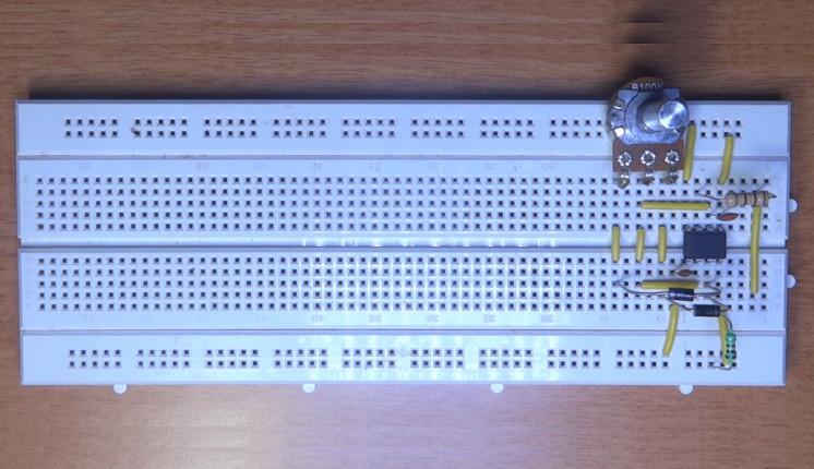
Circuit Design of RGB Bulb
555 Timer IC is used as an astable multivibrator in this project. For the first 555 IC, which is connected to Red LED, Pins 1 and 8 are connected to Ground and Vcc respectively. Pin 4 is an active low reset pin and hence it is connected to Vcc for normal operation. Pin 5 is connected to ground via 10 nF capacitor. For the astable operation, the following connections are made. A 1 KΩ resistor is connected between supply and Pin 7. Pins 2 and 6 are short and a decoupling capacitor is connected from Pin 2 to ground. A 100 KΩ POT is connected at Pin 7 via two switching diodes. The wiper of the POT is connected to Pin 6. A Red LED is connected from Pin 3 via 100Ω resistor. Similar connections are made with respect to other two 555 ICs associated with Green and Blue LEDs. All the LEDs are placed close by and covered with a white plastic or glass dome in order to give it a bulb like structure.
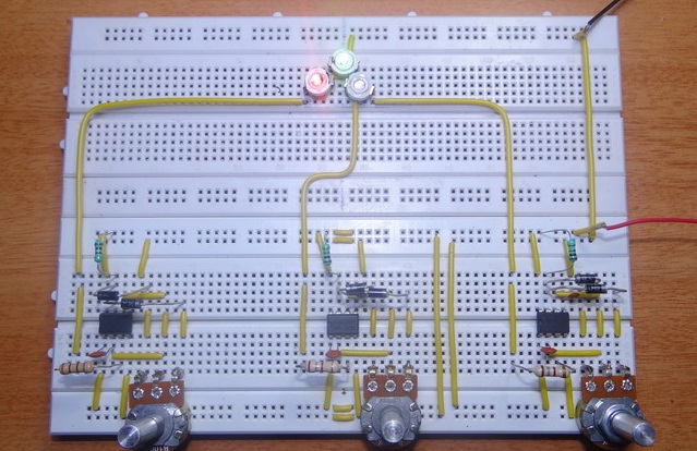
Working of RGB LED Bulb
RGB LEDs can be used to illuminate an area with different colors. There are different RGB bulbs that are available in the market which allow the user to control the luminescence and color with the help of a remote control. In this project, we designed a simple RGB bulb based on three individual LEDs that can be constructed easily with simple hardware. The working of the circuit is explained below. In order to generate different colors using three LEDs: Red, Green and Blue, we need to control the intensity of individual LEDs. 555 Timer IC is used to control the brightness of the LED by implementing Pulse Width Modulation or PWM technique. PWM is a mechanism where the width of the pulse is varied and as a result the Duty Cycle can be controlled. Duty Cycle is the relation between ON time and OFF time. It is the ratio of ON time or Active time in a period to total time of the period where the total time is sum of ON time and OFF time. For a period of 10ms, if the duty cycle is calculated as 50%, then the ON time is 5ms and OFF time is 5ms. If the duty cycle is increased to 80%, the ON time increases to 8ms and OFF time is 2ms. Higher the Duty cycle, more the ON time and brighter the LED. The Duty cycle i.e. ON and OFF time of the Pulse is dependent on the charging and discharging time of the capacitor connected at Pin 6. The two switching diodes connected to Pin 7 along with the POT help in charging and discharging of the capacitor. When the knob of the POT is rotated in clock wise direction, the duty cycle increases as the charging time increases and discharging time decreases. The output is high when the capacitor is charging and hence the brightness of the LED gradually increases. If the knob of the pot is rotated in reverse direction, the duty cycle decreases and the brightness of the LED decreases. The brightness of all the three LEDs: Red, Green and Blue can be controlled by their individual POT knobs and the bulb illuminates in different colors.
• A simple RGB Bulb is designed in this project where the color of the bulb can be controlled manually. • This RGB LED Bulb can be used to generate different colors without the use of any color filters. • The bulb is made from simple components and uses LEDs for luminescence. It consumes very less power and the life time of the bulb can be high. Comment * Name * Email * Website
Δ
![]()
![]()
![]()

![]()
![]()

