Solar concept is not new for us. As non-renewable energy sources are decreasing, usage of solar energy is increased. This solar energy is not only used on the Earth but also used in space stations where no electrical power is available. Here is the simple circuit to charge 12V, 1.3Ah rechargeable Lead-acid battery from the solar panel. This solar charger has current and voltage regulation and also has over voltage cut off facilities. This circuit may also be used to charge any battery at constant voltage because output voltage is adjustable.
Specifications of the Charging Circuit
Solar panel rating – 5W /17V Output Voltage –Variable (5V – 14V). Maximum output current – 0.29 Amps. Drop out voltage- 2- 2.75V. Voltage regulation: +/- 100mV
Solar Battery Charger Circuit Principle: Solar battery charger operated on the principle that the charge control circuit will produce the constant voltage. The charging current passes to LM317 voltage regulator through the diode D1. The output voltage and current are regulated by adjusting the adjust pin of LM317 voltage regulator. Battery is charged using the same current.
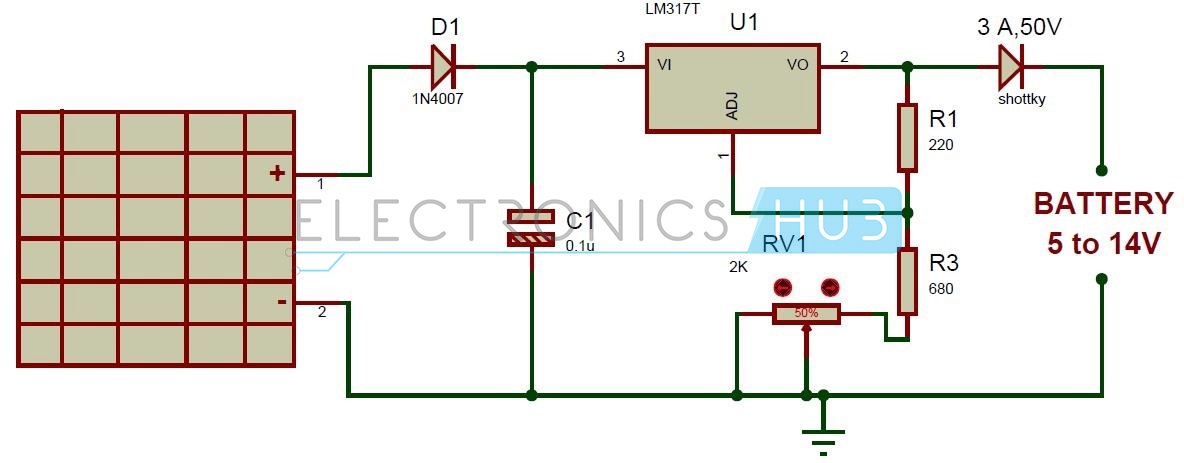
Solar Battery Charger Circuit Diagram:
Circuit Components
Solar panel – 17V LM317 voltage regulator DC battery Diode – 1n4007 Capacitor – 0.1uF Schottky diode – 3A, 50V Resistors – 220, 680 ohms Pot – 2K Connecting wires
LM317 Datasheet
Solar Battery Charger Circuit Design
Circuit must have adjustable voltage regulator , so Variable voltage regulator LM317 is selected. Here LM317 can produce a voltage from 1.25 to 37 volts maximum and maximum current of 1.5 Amps. Adjustable Voltage regulator has typical voltage drop of 2 V-2.5V .So Solar panel is selected such that it has more voltage than the load. Here I am selecting 17v/5w solar panel. Lead acid battery which is used here has specification of 12v/1.3Ah. In order to charge this battery following are required. Schottky diode is used to protect the LM317 and panel from reverse voltage generated by the battery when it is not charging. Any 3 A diode can be used here.
For Charging 12V Battery
Set the output voltage to 14.5 volts(This voltage is specified on the battery as cycle use.)
Charging current = Solar panel wattage/Solar Panel Voltage = 5 / 17 = 0.29A. Here LM317 can provide current upto 1.5A .So it is recommended to use high wattage panels if more current is required for your application.(But here my battery requires initial current less than 0.39Amps. This initial current is also mentioned on the battery). If the battery requires initial current more than 1.5A,it is not recommended to use LM317.
Time taken for charging = 1.3Ah/0.29A = 4.44hours.
Here solar panel has 5Watts Power going into battery = 14.5*0.29 =4 watts Thus 1 watt of power going into regulator.
All the above mentioned parameters have to be taken into account before charging a battery. For 6V Application Set the output voltage to 7.5-8 volts as specified on the battery. calculate the charging current ,power dissipation as shown above. Power Dissipation In this project, power is limited because of the thermal resistance of LM317 voltage regulator and the heat sink. To keep the temperature below 125 degree Celsius, the power must be limited to 10W. LM317 voltage regulator internally has temperature limiting circuit so that if it gets too hot, it shuts down automatically. When battery is charging, heat sink becomes warm. When completing the charging at maximum voltage, heat sink runs hot. This heat is because of excess power that not needed in the process of charging a battery. Current Limiting: As the solar panel provides constant current, it acts as a current limiter. Therefore the circuit does not need any current limiting. Solar Charger Protection: In this circuit, capacitor C1 protects from the static discharge. Diode D1 protects from the reverse polarity. And voltage regulator IC provides voltage and current regulation. Solar Charger Specifications:
Solar panel rating: 20W (12V) or 10W (6V) Vout range: 5 to 14V Maximum power dissipation: 10W (includes power dissipation of schottky diode) Typical drop out value: 2 to 2.75V (depends on load current) Max current: 1.5A (internally it limited to 2.2A) Voltage regulation: +/- 100mV
How to Operate this Solar Battery Charger Circuit?
Solar Battery Charger Circuit Advantages:
Adjustable output voltage Circuit is simple and inexpensive. Circuit uses commonly available components. Zero battery discharge when no sunlight on the solar panel.
Solar Battery Charger Circuit Applications:
This circuit is used to charge Lead-Acid or Ni-Cd batteries using solar energy. (You may get an idea about How a Lead Acid Battery Charger Circuit Works by reading the earlier posts.)
Limitations of this Circuit:
Solar batteries are one of the power tools to make the device function efficiently. As the non-renewable energy sources are decreasing there is a need to increase the usage of solar power. Solar batteries play crucial role to make it happen within no time. But the thing is when you get the solar batteries you need to have the electronic device that supports the solar batteries. My best suggestion is to purchase the Solar Lights Kits that can affix to home gardens, walkways and on the walls. They come at very affordable prices and make the outdoor look more beautiful and romantic especially at night times. You can spend some time with your beloved ones in the presence of bright white light. I want to use a solar panel, but I want to automatically stop charging the battery when it is full as well. I hope someone could reply really quickly. Thanks Then what should i use? I have a 1.4A (initial current) battery Comment * Name * Email * Website
Δ
![]()
![]()
![]()
![]()
![]()

