Resistors can be mainly categorised into Linear and non linear resistors.
What is a linear resistor?
Resistors that obey ohms law are called linear resistors. The resistance of these resistors does not change with the varying current flowing through it. Generally, resistors that obey ohm’s law are
- Fixed resistors
- Variable resistors
Fixed Resistors
Fixed Resistors are those whose resistance value is fixed. Manufacturer sets a fixed value to it. Ideally fixed resistors should work independent to changes in temperature, voltage and frequency. This is not possible practically as all resistor materials have temperature coefficient which leads to temperature dependency. The stray capacitance which is present in all resistors will result in impedance and hence the actual resistance will be different from expected. Fixed resistors are available in different sizes, shapes, leaded, lead less, etc. Some of the fixed resistors are Carbon Composition Resistor. Film resistors. Wire wound.
Carbon Composition Resistors
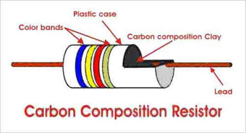
Carbon Composition Resistors are commonly used resistors. Because of their construction these resistors are manufactured at low cost. These resistors are composed of finely ground carbon along with ceramic clay acting as a binding agent. The proportions of carbon and clay are the factor in determining the resistive value. Resistance is higher when the quantity of carbon is lesser.
They can be manufactured in wide range of values ranging from 1Ω to a high value as 22 MΩ. The advantage of carbon resistors is its ability to remain undamaged from high energy pulses, available at very low cost and good durability. The disadvantages are high sensitivity to temperature, unstable noise properties and stability issues when hot. They are easily affected by humidity and hence the tolerance is only 5%. They also have a low-medium range power rating i.e. < 5W. Carbon composition resistors are suitable for high frequency applications as they have low inductance.
Film Type Resistors
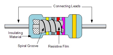
Film type resistors are manufactured by a process called film deposition technique. Once the film is deposited on the insulating material, it is cut into a spiral helix pattern with the help of a laser. The resistive value is controlled or maintained by controlling the thickness of the film that is deposited. Two types of Film resistors are
- Thin Film Resistors
- Thick Film Resistors
Thin film resistors are manufactured by depositing a resistive layer on an insulating base like ceramic. The thickness of the resistive film is equal to or smaller than 0.1 micro meters. Vacuum deposition is the technique used to deposit the resistive film on the ceramic. The resistive material which is often an alloy of nickel and chromium called Nichrome is sputtered on an insulator base which is ceramic. This process will create a uniform film of 0.1 micrometer thick. The thickness of the metallic film can be controlled by controlling the time of sputtering. Patterns are created by laser trimming process on the dense and uniform layer to create and calibrate the resistive path and resistance value. Thin film resistors can be produced as SMD resistors or axial leaded resistors. Because of their high tolerance and low temperature coefficient, thin film resistors are used in precision applications. Examples of thin Film resistors are
- Metal Film,
- Carbon Film and
In metal films, nickel metal is used as resistive element and tin oxide in case of metal oxide films.
Metal Film type resistors have much higher tolerance and better temperature stability when compared to carbon resistors. Hence they are used in applications like active filters where low temperature coefficient and tight tolerance are required. Carbon film resistors are better than carbon composition resistors. Carbon film resistors are used in applications where the operating voltage and temperature is high like laser and radar.
In thick film resistors, the thickness of resistive film is nearly 1000 times thicker than that in thin film resistors. The main difference between thick film and thin film resistors is the procedure for applying the resistive film. The resistive film in thick film resistors is made from a mixture of a binder, carrier and metal oxide. Glass frit bonding is used to bind the mixture. Carrier is the extract of organic solvent and oxides of iridium or ruthenium are used. This mixture is made as a paste and the resistive film is produced by applying this paste on to a ceramic base using stencil and screen printing process. Thick film resistors can be used in applications where less cost is important, high power is handles and high stability is important. Example of Thick film resistor is
- Metal Oxide Film.
Metal oxide resistors have much better temperature stability and better surge current capacity.
Wire Wound Type Resistors
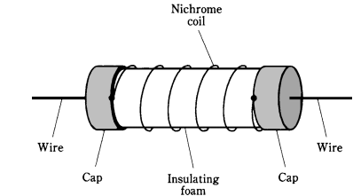
Wire wound resistors are most precise and high power rated resistors. The construction of wire wound resistors involves a winding of thin metal or metal alloy wire around an insulating substrate. Generally the metals used are manganin or constantan and a nickel chromium alloy which is also called as nichrome is used in case of metal alloy. The resistive value can be varied by varying wrap pattern, diameter, length and type of alloy.
The resistance tolerance of wire wound resistors is as tight as .005% and the power ratings are in the range of 50W-300W. These are precision wire wound resistors. In case of power resistors, the tolerance is 5% and the power rating is in the range of kilo watts. They are limited to low frequency applications because of the nature of their construction. Since there is a metal wire wound as a coil around an insulator, they act as inductors. This results in reactance and inductance and when used in A.C circuits there is a chance of phase shift when operated at higher frequencies. There is a possibility to overcome this limitation by winding each half of wire in different directions. This will cancel each other’s inductive effect. These resistors are called as Non-Inductive Wire Wound Resistors. Normally the cost of wire wound resistors is higher when compared to carbon composition resistors. In high frequency applications Non-Inductive Wire Wound Resistors can be used but their cost is more than normal wire wound resistors. Wire wound resistors are used in many applications. Some of them are circuit breakers, transducers, temperature sensors and current sensors.
Variable Resistors
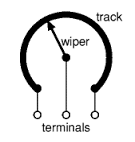
Variable resistors are those in which the value of resistance can be varied or adjusted. The working of a variable resistor can be explained with the help of following diagram.
The resistance path is provided by track and the terminals of device are connected to track. Wiper is used to increase or decrease resistance through its motion.
Potentiometer
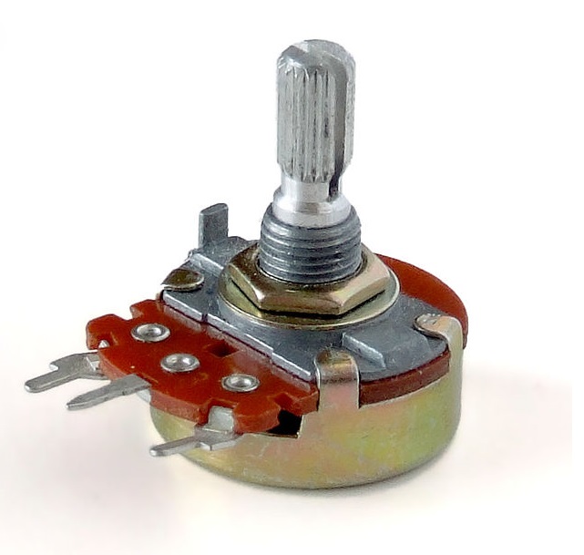
A potentiometer or pot is an electro mechanical resistor with three terminals and is the most commonly used variable resistor.
The two terminals on the either end will deliver a constant resistance which is the formal resistance. The terminal in the centre is movable and is called Wiper. This movable wiper maintains contact with the resistive surface. The resistance between first terminal and the wiper plus the resistance between wiper and second terminal is equal to the formal resistance of the device. The name potentiometer is given to this device as it adjusts voltage using voltage divider principle. While wiper is a rotating contact, some potentiometers have continuously adjustable tapping points which are contacted with the third terminal called tappers and they also act as continuously adjustable voltage divider. The best application is their use in tuning circuits an in radio receivers.
Preset
Preset is a variable resistor which is used in occasional adjustment conditions. Generally presets are mounted on printed circuit board and are adjusted using the rotary control present on top of it with the help of a screw driver. In contrast to potentiometers where the resistance varies linearly, the resistance in preset varies exponentially. The symbol of a preset is as shown below.
Presets are made available in single turn and multi turn operations. Presets are used in designs where the value of the resistance is set in the circuit during the time of production. Due to their sensitivity, presets are often used in sensing circuits like temperature or light sensing.
Rheostat
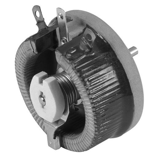
A rheostat is a two terminal variable resistor. In rheostat, one end of resistive track of a variable resistor and its wiper terminal are connected to the circuit. This connection will limit the current in the circuit according to the position of the wiper.
Rheostats are used to control the resistance without interrupting the flow of current. Because of this significant flow of current, rheostats are made as wire wound resistors. Rheostats are used in applications where current is more important than power rating. They are generally used in tuning circuits and power control applications.
Non linear Resistors
As the name indicates their resistance value varies with the varying Current flowing in the resistor.Some non linear resistors are
Varistor LDR Thermistor
Varistor
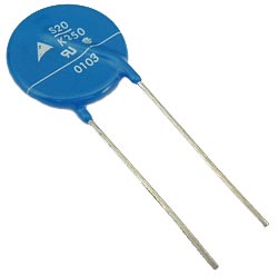
It is an electronic component with non-linear current voltage characteristics. The resistance in varistor is changed according to the change in voltage across it. This makes it a voltage sensitive device hence it is also called Voltage Dependent Resistor.
The resistance of varistor is very high under normal operating conditions. But the resistance decreases dramatically when the voltage increases beyond the rated value of varistor. Metal oxide Varistors are most common type of varistors. Grains of Zinc oxide are used because it provides P-N diode characteristics. Hence it is used to protect electronic and electrical circuits from over voltage surges.
Light Dependent Resistor (LDR)
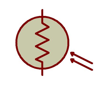
Light Dependent Resistors or Photo resistors are light sensitive resistors whose resistance varies according to the intensity of the light incident on them. The symbol of Light dependent resistors is
Light dependent resistors are made of semiconductors with high resistance. In absence of light or in dark, the resistance of light dependent resistors is very high usually in the range of Mega Ohms (MΩ). In absence of light or in dark, the resistance of light dependent resistors is very high usually in the range of Mega Ohms (MΩ). When light is incident on the surface of light dependent resistors, its resistance value decreases.
Thermistor
Thermistor is a resistor whose resistance value varies with the temperature. It is a type of transducer. These are mostly used for measuring the temperature. There are two types of thermistors. NTC (Negative Temperature Coefficient) , PTC (Positive temperature Coefficient) As the temperature increases, resistance of the thermistor decreases for NTC thermistor and for PTC Resistance increases with increase in temperature. They differ from temperature detectors. RTD are useful for large temperature ranges where as these thermistor are useful from -90 to 1300
Other types
Resistors can be further divided based on mounting, power rating.
Resistors Types Based on Termination and Mounting
SMD Resistors
Surface Mount Devices (SMD) are produced as a result of a technique called Surface-mount Technology (SMT). The development of Surface-Mount Technology and Surface Mount Devices is a result of requirement of smaller, faster, cheaper and more efficient components by PCB manufacturers.
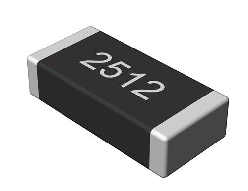
SMD resistors are smaller than their through-hole counterparts and are generally rectangular but sometimes oval in shape. These rectangular chips have very small metal leads or metalized areas at either ends which are used to make contact with the PCB and therefore eliminating the need for holes on PCB and wire leads on resistors. A single SMD resistor is as shown in the figure.
SMD resistors consist of an insulator substrate which is generally ceramic and a layer of metal oxide film is deposited on this substrate. The value of resistance is determined by the thickness of the film. Because of their small size they are suitable for circuit boards. They have very little inductance and capacitance and can perform well at radio frequencies.
Through-hole Resistors
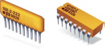
Through-hole is a mounting technique where the components are inserted into holes that are drilled on a PCB. For this purpose, the electronic component consists of small metallic leads. All the resistors with leads coming out of them for contact purpose come under Through-hole resistors. Through-hole resistors are available in carbon composition resistors, carbon film resistors, metal film resistors, metal oxide resistors, wire wound resistors and many others. Apart from discrete components, through-hole resistors can be found as pack of resistors with the usage of Dual in-line package and Single in-line package techniques.
These SIP and DIP resistors are generally used in resistor ladder networks, pull-up and pull-down networks, bus terminators etc.
Network Resistors
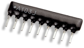
Network resistors are single package resistors with two or more resistors. They generally come in Single in-line package or Dual in-line package. These SIP and DIP resistors are generally used in resistor ladder networks, pull-up and pull-down networks, bus terminators etc.
Resistor networks are used to reduce the board space, improve reliability, reduce solder connections and improve tolerance matching. Generally resistor networks are used in resistor ladders, bus terminators and small computer system interface terminators. They are available as both surface mount devices and through-hole devices.
Resistor color codes Comment * Name * Email * Website
Δ





![]()