Welding Symbols are a graphical way to convey information about a welding joint. Instead of using an arrow and saying ‘weld here’, a weld symbol carries more useful information that can be easily understood by the welder, engineer, foreman, supervisor and architect. Hence, Welding Symbols are widely used in engineering drawings by welders and engineers to convey essential information like type of the weld, size of the weld, location of the weld and other supplementary information as well.
Why Do We Need to Specify Welds?
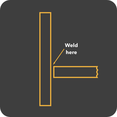
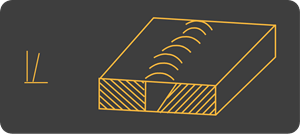
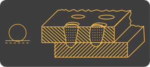
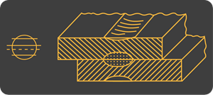
Consider the following image is given to a welder. The message ‘weld here’ can be interpreted in many ways and hence such messages are always followed by certain instructions.
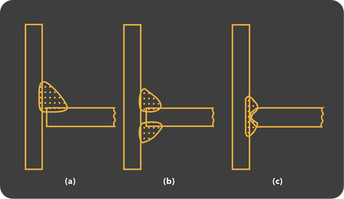
Any one of the following images can be given in addition to the above image. The first image (a) means a single fillet weld, which is the simplest of all and also cheap to apply. The second image (b) means a double fillet weld. It is slightly difficult to apply and takes longer time. For this weld to be successful, access to both sides should be available. Finally, the third image (c) means a T-butt or groove weld. It is the most complex and expensive of the three as the horizontal object needs an edge preparation.
Hence, it is clear that more information on the weld joints must be specified at the design / drawing stage to avoid errors and properly estimate the time and cost of the welding process.
Advantages of Weld Symbols
From the above explanation, we have concluded that properly specifying the welds is a necessity for a smooth flow of work. But the above-mentioned pictorial illustration of the weld is not the easiest or the preferred method. Similar to electrical symbols in electrical circuits, we also have Welding Symbols. Specifying Welds with symbols rather than pictures is a lot simpler as you don’t have to spend much time in explaining the type, shape and size of the weld. Hence, most Engineering Drawings related to welding jobs use Weld Symbols to represent all the information associated with a weld.
Welding Standards
There are two main standards for defining welding and brazing terms, symbols etc. One is the ISO 2553 published by International Organization for Standardization. The other is the ANSI / AWS A2.4-98 published by the American Welding Society. The terms and symbols might be different in these two standards.
Elements of a Welding Symbol
Before looking at some of the Basic Weld Symbols, let us try to understand the elements of a welding symbol and what kind of information does a symbol convey. The following is the list of elements that may be a part of a typical welding symbol.
Reference Line Arrow Basic Welding Symbol Supplementary Weld Symbols Finish Symbols Dimensions Specifications, Process Tail
To understand the elements of a weld symbol more clearly, let us use the following image, which describes how a typical welding symbol is drawn and also the standard location of the above-mentioned elements.
Reference Line It is a horizontal line that is an important part of a completed welding symbol and all the information related to the weld is drawn on or around it. The positioning of the reference line is also important as it is usually drawn close to the weld joint. All the other symbols and information must be properly placed as per the symbol standards on or around this reference line. Arrow Another important and required part of a completed welding symbols is the Arrow. It connects the reference line with the Arrow Side of the joint and can be placed at one or the other end of the reference line. The arrow can point in any direction, up down, left, right or it can even point toward the tail. Sometime, a welding symbol can contain multiple arrows. Here, there are two important terms we need to be aware of regarding the arrow. They are the Arrow Side and the Other Side. Arrow Side of the Reference Line is that side of the weld joint to which the arrow points to. If symbols are placed on the Arrow Side of the Reference Line, then they refer to the Arrow Side of the weld joint. If the symbols are placed on the other side of the reference line (other than the Arrow Side), then they refer to the Other Side of the weld joint.
Other Information Describing the Weld
T: It is a part of the Tail to specify information for a particular weld such as change in welding process or electrode. Tail may be omitted if there aren’t any specifications or reference. S: Depending on the type of Weld, it can indicate any of the following: Depth of preparation in case of a Groove Weld Size of Fillet Weld Size of Plug Weld or Slot Weld Shear Strength in case of Projection Weld E: In case of Groove Weld, it represents the Effective Throat Size or Weld Size. It indicates the Leg Size in case of Fillet Weld. An important point is that the Effective Size dimensions for Groove Weld are always placed inside parenthesis whereas the Leg Size dimensions for Fillet Weld are placed without parenthesis.
NOTE: Both S and E are always placed to the left of the weld symbol on the reference line irrespective of the arrow.
R: In case of Groove Weld or Butt Joint, this is the dimension for the Root Opening. In case of Plug Weld or Root Weld, this indicates the depth of filling. A: In case of groove Weld, this represents the Included Groove Angle. For Countersunk Plug Welds, this represents included angle of the countersink. F: This is where the method of obtaining required contour is indicated. Some of the methods through which contours may be obtained are: Grinding (G), Chipping (C), Machining (M), Rolling (R), Hammering (H) or unspecified (U). —: The horizontal line between F and A is the place of the contour symbol of the finished weld. L: It indicates the Length of the Weld. It is always placed on the right of the weld symbol irrespective of the location of the arrow. P: If welding is intermittent and spacing between the welds is indicated, then this Indicates the Pitch Spacing or Center-to-Center Spacing of the weld N: Indicates the Number of Welds (Spot, Seam, Stud, Plug, Slot or Projection) required.
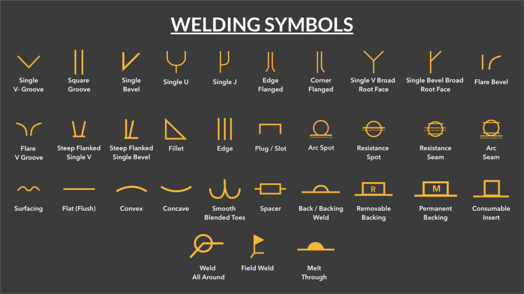
Different Types of Welding Symbols
Now that we have seen a little bit about elements of a Weld Symbol, we will now take a look at different welding symbols. First, we will list some Basic Welding Symbols, which most commonly used in drawings. Next, we will see some Supplementary Welding Symbols, which can be used to convey additional information about a weld.
Basic Welding Symbols
Following image shows some of the commonly used Welding Symbols. The top part of the image consists of Symbols for different types of Groove or Butt Welds. This includes V Groove Weld, Square Groove Weld, Bevel Groove Weld, U, J, etc.
The bottom part of the image consists of Fillet Weld, which is perhaps the most frequently used type of weld, Edge Weld, Plug / Slot Weld, Spot Weld etc. Let us now see about different Weld Symbols in detail. Groove Welding is the second popular type of weld after Fillet and it involves edge preparation to form one of the Groove Weld Shapes (V, U, J, Bevel, etc.) or Square Groove with square edges.
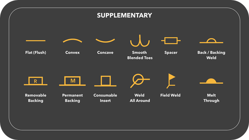
Supplementary Welding Symbols
The supplementary welding symbols are used to provide additional information about the weld joints.
Location of Welding Symbols
Let us now understand the location significance of the symbols. First, we will see a couple of examples for Groove Welds and then we proceed with Fillet Welds.
Groove Welds
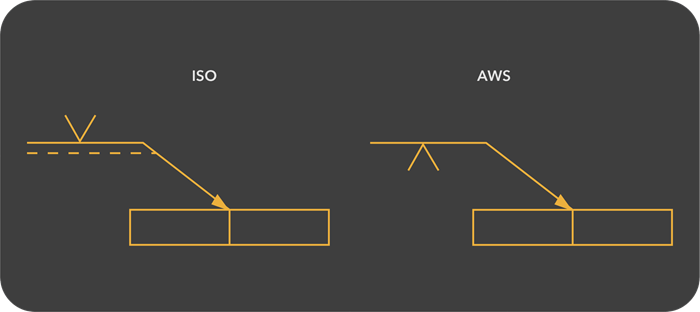
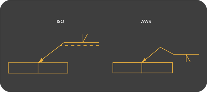
The following image shows the location of Groove Welding Symbols. Symbols in both ISO and AWS standards are shown for reference. In the first image, a Single V Groove Weld is shown where the welding symbols are located on the reference line and the arrow is pointing to one side of the joint. The weld can be in a plane view or a cross section. Here, we used the arrow to point to the weld in a cross-section.
In the second image, a Single Bevel Groove Weld is shown where the arrow points to the edge of the joint which must be prepared for bevel.
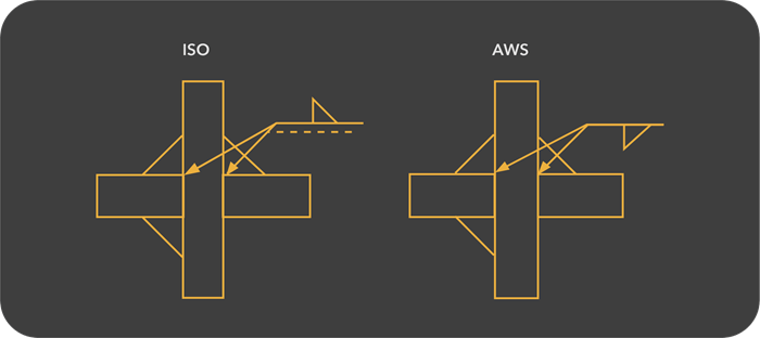
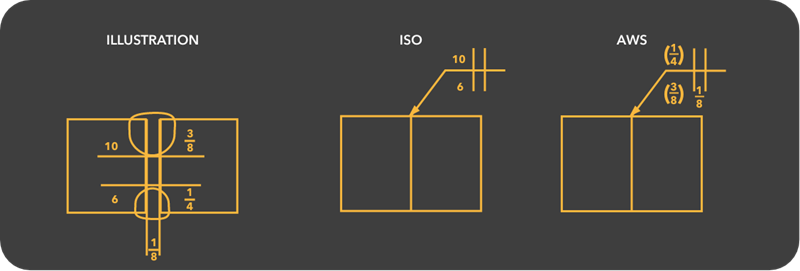
Fillet Welds
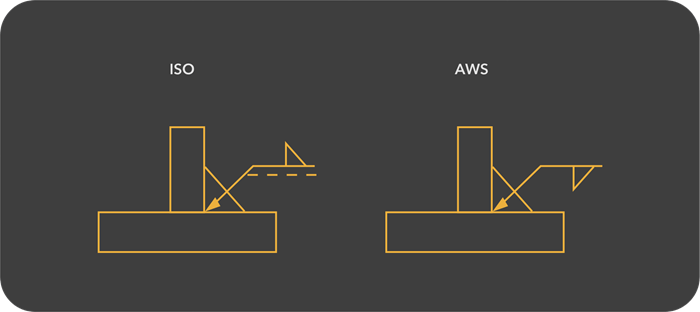
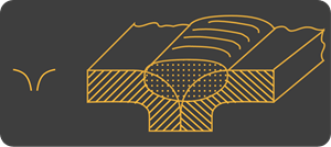
Similar to Groove Welds, the Symbols for Fillet Welds are also located on a reference line, which is then connected to an arrow pointing to one side of the joint. To demonstrate the same, let us take ‘T-Joint’ and ‘Cruciform Joint’ as welding joints and see the location significance of Fillet Welds. In the first image, an end view of a T-Joint is shown with a single Fillet Weld.
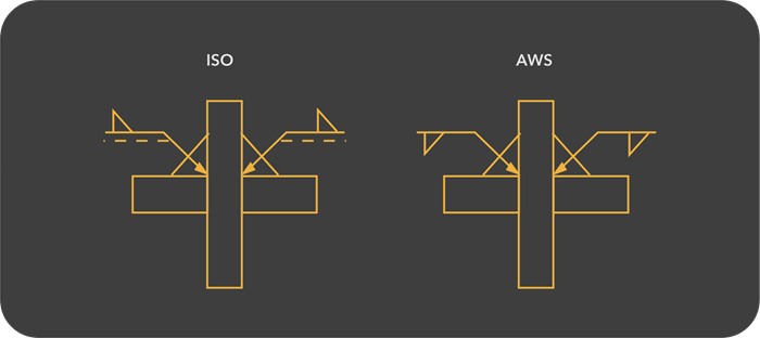
In the second image, an end view of a Cruciform Joint is shown with two single fillet welds.
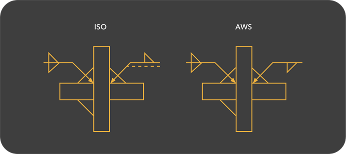
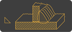
In the next image, an end view of a Cruciform Joint is shown with a double fillet weld on the left side and a single fillet weld on the right side.
In the last image, it is an alternative way to represent the second image where two arrows are used with a single reference line. This method can be used as per ISO Standards but cannot be used as per AWS Standards.
Dimensions in Weld Symbols
Size of the Welds is also an important specification in some welds. Both ISO and AWS Standards have their own way of specifying the necessary dimensions of the welds.
Groove Welds
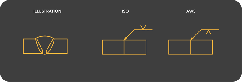
Fully Penetrated Groove Welds
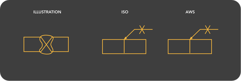
The following images show the illustration, ISO Symbol and AWS Symbol for a Fully Penetrated Single V Groove and Symmetrical Double V Groove Welds.
Partial Penetrated Groove Welds
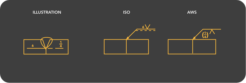
Both ISO and AWS Standards allows specification of the size of the Groove Weld on the left of the weld symbol. In ISO Standard, the number is placed directly and the dimensions are usually in millimeters. In AWS Standard, the numbers are placed in brackets and the dimensions are in inches. The following image shows a Partial Penetration of a Single V Groove Weld.
A similar approach can be applied to Square Groove Weld as well. The following image shows a Partial Penetration Square Groove Weld. In AWS, additional information for edge preparation can be indicated. The size of gap between the plates is mentioned between the sides of the weld symbol.
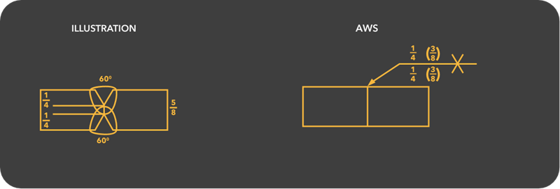
Groove Weld Dimensions
All the details of a Groove Weld such as Bevel Angle, Root Face, Gap and Sizes of Welds can be mentioned as per the AWS Standard. The following image shows 5/8-inch plate with 600 Bevel Angle, Depth of Bevel is 1/4 inch and weld size is 3/8 inch.
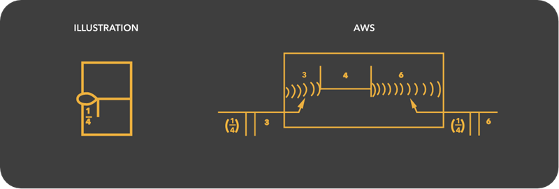
Length of Groove
If the length of the Groove Weld is not mentioned, then it means the whole length of the joint must be welded. But sometimes length of the weld is smaller than the length of the joint or the welding may be intermittent. In this case, we can specify the length and location of the weld with a number on the right of the symbol. The following image shows an AWS Standard Symbol which has information on intermittent Square Groove Welds along with hatching.
Fillet Welds
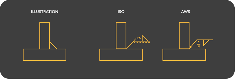
Fillet Weld Sizes
As per ISO Standard, the size of the Fillet Welds can be mentioned using Leg Length (z) and Throat Thickness (a). The dimension is placed on the left of the weld symbol and additionally, it is preceded by letter z (for leg length) or a (for throat thickness). In AWS Standard, the size of the fillet weld is always the Leg Length and the number is placed on the left of the weld symbol. The following image shows a Fillet Weld both in ISO and AWS Standards with leg length of 6mm (1/4 inch).
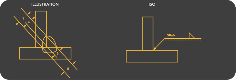
Deep Penetration Welds
The following image shows an ISO Standard Symbol for deep penetration welds and the effective weld throat is represented by S, which is placed in front of the throat thickness.
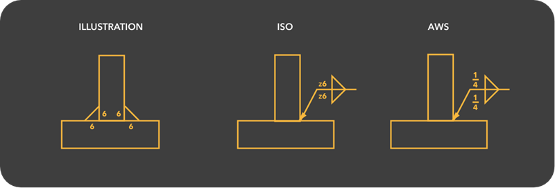
Double Fillet Welds
All the dimensions in a Double Fillet Weld are repeated even if they are identical. The following image shows the same.
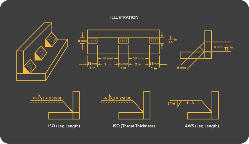
Longitudinal Fillet Welds
If the weld is intermittent and not continuous, then the length of the weld and also the gaps between the welds can be mentioned. The following image shows a plan view and cross section of an intermittent fillet weld along with the ISO and AWS Standard symbols.
Bonus – Illustrations for Welding Symbols
The following table has demo illustrations for different weld symbols described in the article. You can use these illustrations as a reference for a better understand of all the welding symbols. Comment * Name * Email * Website
Δ
![]()
![]()
![]()

![]()


![]()
![]()

